Holographic Microscope, Holographic Image Generation Method, and Method for Acquiring Data for Holographic Image

a tomographic image and holographic microscope technology, applied in the field of optical interference tomographic image pickup technology, can solve the problems of inability to uniquely determine the tomographic image derived based on only the phase of the object light has an error, and becomes an image of bad s/n ratio, etc., to achieve the effect of high speed, short time and high speed

Active Publication Date: 2015-09-24
UNIV OF HYOGO
View PDF3 Cites 20 Cited by
  • Summary
  • Abstract
  • Description
  • Claims
  • Application Information

AI Technical Summary

Benefits of technology

[0035]According to the data acquisition method for a holographic tomographic image of the present invention, data for tomographic images can be acquired and recorded at high speed in a short time, because the data for tomographic images can be acquired only by acquiring three kinds of holograms about each wavelength by a wavelength-scanning without performing any mechanical scan of an optical system. According to the method for generating a holographic tomographic image of the present invention, mechanical scanning of an optical system is unnecessary, because a tomographic image is generated using holograms acquired using illumination lights Q and reference lights R and L on which wavelength-scanning is carried out. Further, it is possible to generate a tomographic image of large S / N ratio on a selected tomographic plane without being disturbed by the object light from other tomographic plane or layer and to generate a three-dimensional volume image by using a set of those tomographic images, because the holograms of both of the object light O and the illumination light Q are used. According to the holographic tomographic microscope of the present invention, it is possible to generate a distortionless tomographic image correctly without using an imaging lens because spherical wave reference lights R and L are used, and also image data can be acquired and stored at high speed because the mechanical scan is unnecessary. Therefore, according to this tomographic microscope, high-speed continuous tomographic image pickup of the living tissues under low energy illuminations is possible, and it is possible to realize price reduction and miniaturization of such an equipment easily.

Problems solved by technology

However, the tomographic image pickup method by the digital holography, as shown in the above-mentioned Non-Patent documents 1 and 2 can eliminate the need for mechanical scanning of the optical system in the conventional OCT, but it has a practical problem.
In other words, since an object lights is generally emitted from each point in a translucent object in tomographic image acquisition of the translucent object, it is impossible to determine the phase of the object light uniquely.
Therefore, and therefore the tomographic image derived based on only the phase of the object light has an error and becomes an image of bad S / N ratio.
In particular, when reflected lights generated in the object overlap continuously in the depth direction, it becomes difficult to derive a practical tomographic image by such a tomographic image pickup method.
Moreover, the holographic microscope, as shown in the above-mentioned patent document 2, can reconstruct an exact high resolution three-dimensional moving images without distortion, however, it is not developed for acquisition and observation of tomographic images.
However, since lateral resolution, i.e., the resolution in the direction perpendicular to the propagation direction of the light, is determined by the spot size of an illumination light, it is difficult to achieve high resolution for it and the lateral resolution has remained one digit or more smaller than the optical microscope.
Moreover, the conventional OCT cannot diagnose, for example, early stage cancer or many other diseases because its resolution is still low.
Additionally, it is difficult for the conventional OCT to perform real time image pickup of the tomographic image of a moving subject because it cannot perform a high-speed image pickup.

Method used


Image

  • Holographic Microscope, Holographic Image Generation Method, and Method for Acquiring Data for Holographic Image
  • Holographic Microscope, Holographic Image Generation Method, and Method for Acquiring Data for Holographic Image
  • Holographic Microscope, Holographic Image Generation Method, and Method for Acquiring Data for Holographic Image

Examples


working example

[0151](Working Example)

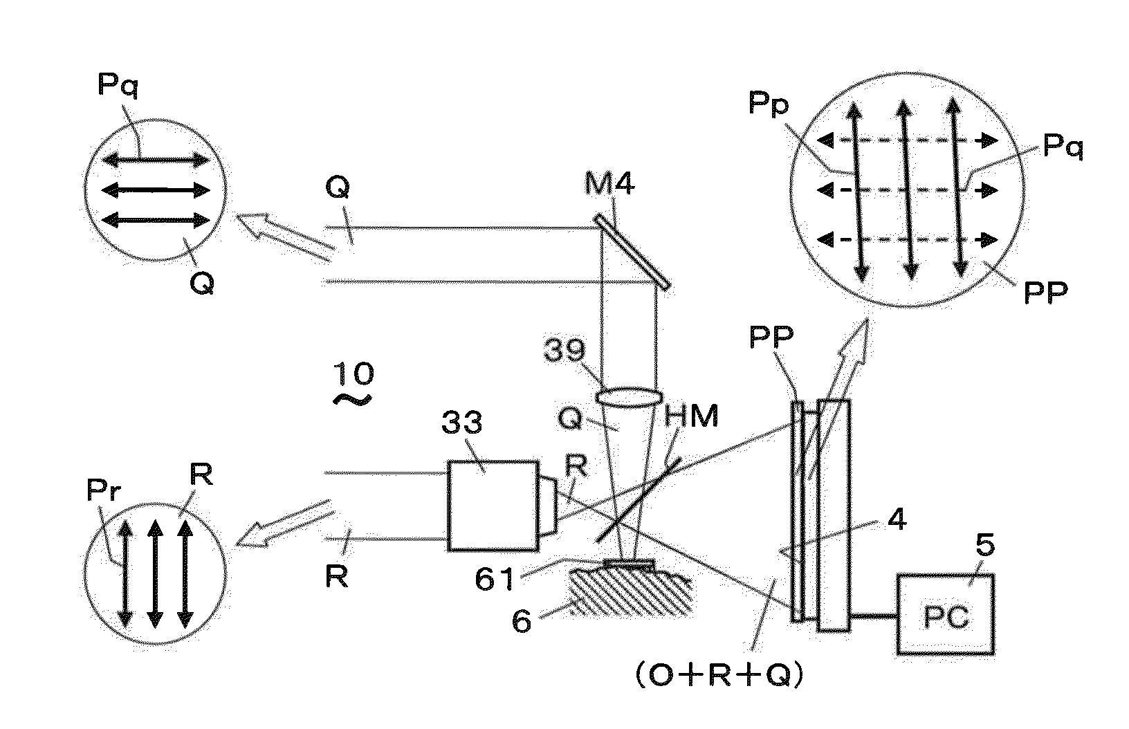
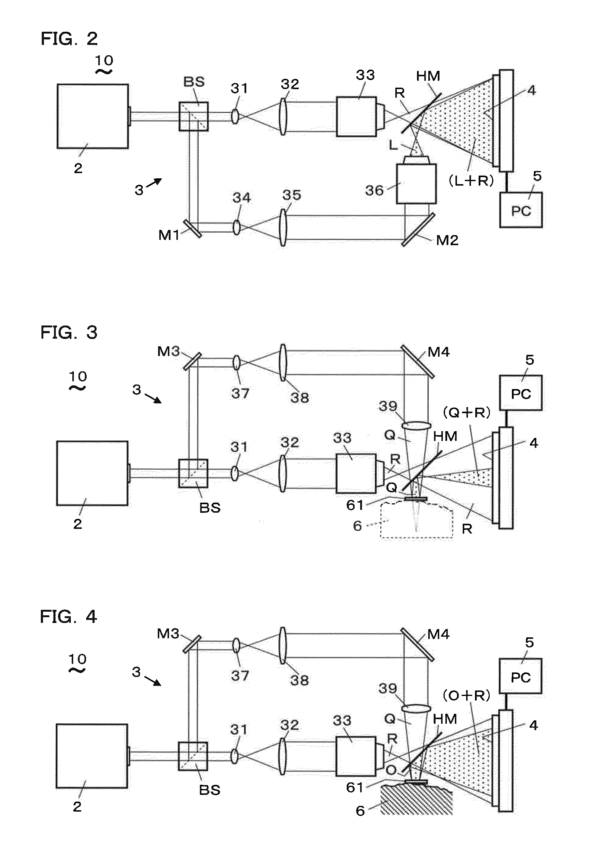
[0152]FIG. 23 to FIG. 27 show a working example of the holographic tomographic microscope, the method for generating the holographic tomographic image, and the data acquisition method for holographic tomographic images. Recording of the reference lights R and L was performed using equipment having the constitution shown in FIG. 2, FIG. 3, FIG. 5, and FIG. 6, and recording of the object light O was performed using equipment having the constitution shown in FIG. 4 and FIG. 7. A USAF test target arranged in the air was used as the translucent object 6 for a photographic subject. The USAF test target and the photo-detector 4 are arranged so that their surfaces may become parallel mutually in the optical path. A Littman type wavelength variable laser was used as the light source 2, and a CCD camera (effective pixels of 4872×3248 pixels, 7.4 gm of pixel pitch) was used as the photo-detector 4. The USAF test target was irradiated with a light beam (the illumination l...


PUM


Abstract

The present method includes a data acquisition process and tomographic image generation processes. In the data acquisition process, holograms of an object light and so forth are acquired for each light with a wavelength by changing the wavelengths of the illumination light, off-axis spherical wave reference light, and inline spherical wave reference light. In the tomographic image generation process, a reconstructed light wave of the object light and a reconstructed light wave of the illumination light on a reconstruction surface are generated from these holograms. A reconstruction light wave with adjusted phase is added up for each wavelength to generate a tomographic hologram. From this, an accurate and focused tomographic image without distortion can be generated.

Description

TECHNICAL FIELD[0001]The present invention relates to an optical interference tomographic image pickup technology, and relates to a tomographic microscope, a method for generating a tomographic image, and a data acquisition method for a tomographic image which use holography.BACKGROUND ART[0002]Conventionally, a technology of an optical coherence tomography (OCT) attracts attention as state-of-the-art medical diagnostic technology which is non-invasive and harmless to a human body, and equipment development and application research to living body measurement have been promoted energetically. OCT is a technology of acquiring the information on an objective optical response structure to the depth where light can approach from the objective surface, and is applied to the examination of the fundus etc. The OCT, which is proposed from the beginning and put into practical-use, uses a laser light which is a light beam having a narrowed spot size. The laser light is divided into an illumina...

Claims


Application Information

Patent Timeline
Patent Type & Authority Applications(United States)
IPC IPC(8): G03H1/00G03H1/04
CPCG03H1/0005G03H2001/005G03H1/0443G03H2001/0445G03H2001/266G03H2222/42G03H2222/52G02B21/06G02B21/365G03H2222/13G03H1/0866G03H2001/0447G03H2001/0456G03H2001/0825G03H2001/0883G03H2226/02G01B9/02091G01B9/02047
Inventor SATO, KUNIHIRO
Owner UNIV OF HYOGO
Why Eureka
Try Eureka