Organic light emitting element
a light-emitting element and organic technology, applied in the field of organic light-emitting elements, can solve the problems of large electron into the emission layer, difficult to subject the compound to sublimation purification, and large amount of electrons, and achieve the effect of stable performance in the air
- Summary
- Abstract
- Description
- Claims
- Application Information
AI Technical Summary
Benefits of technology
Problems solved by technology
Method used
Image
Examples
example 1
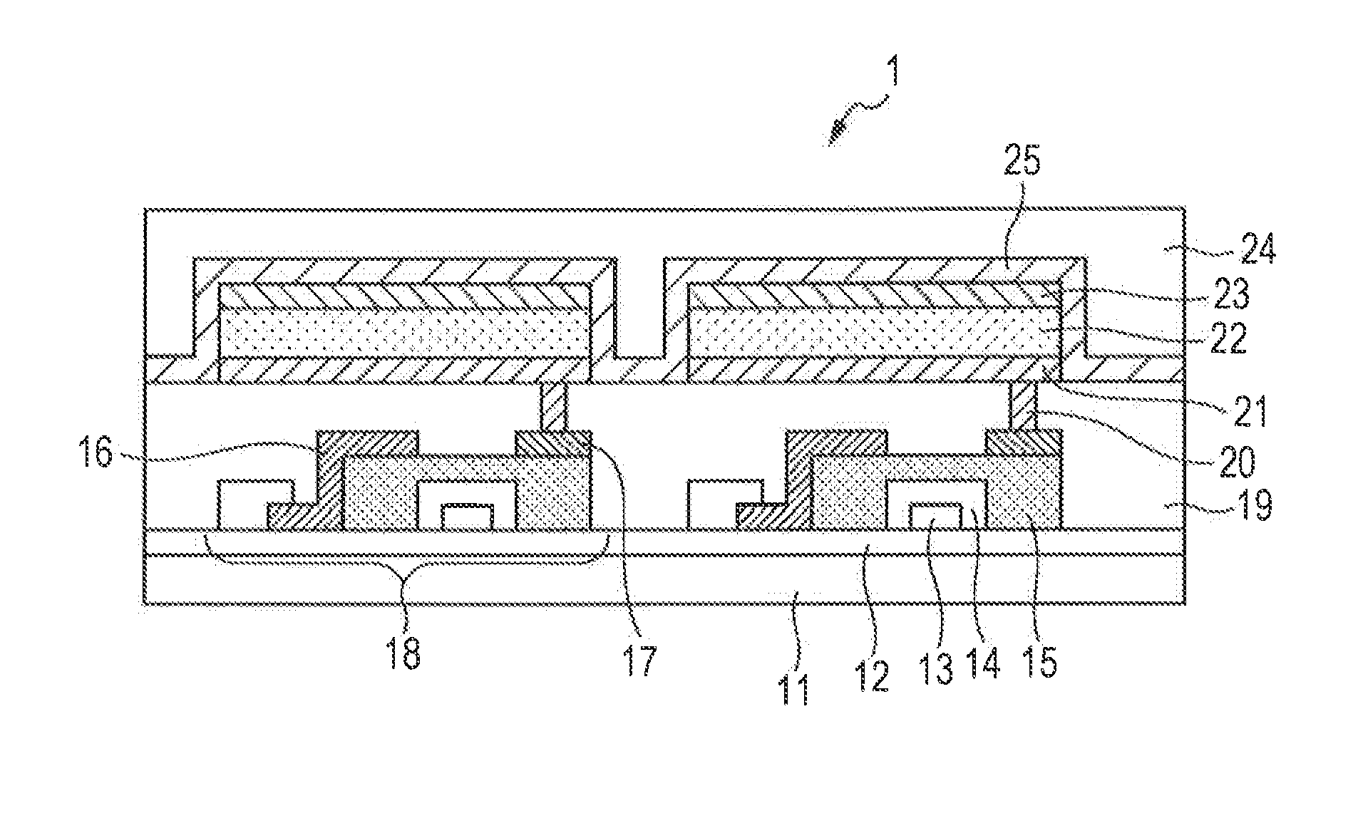
[0179]In this example (Example 1), an organic light emitting element of a bottom emission construction in which an anode, a hole transport layer, an electron blocking layer, an emission layer, an electron transport layer, an electron injection layer, and a cathode were formed in the stated order on a substrate was produced by a method to be described below.
[0180]Indium tin oxide (ITO) was formed into a film on a glass substrate by a sputtering method. Thus, the anode was formed. At this time, the thickness of the anode was set to 120 nm. Next, the substrate having formed thereon the anode was sequentially subjected to ultrasonic washing with acetone and isopropyl alcohol (IPA), and was then subjected to boil washing with IPA, followed by drying. Further, the dried product was subjected to UV / ozone washing. The substrate treated by the foregoing method was used as a transparent conductive supporting substrate (ITO substrate) in the next step.
examples 2 to 7
[0183]Organic light emitting elements were each produced by the same method as that of Example 1 with the exception that in Example 1, the constituent materials for the electron injection layer were changed as shown in Table 2 below. The resultant organic light emitting elements were evaluated for their element characteristics by the same method as that of Example 1. Table 2 shows the results.
examples 8 to 11
[0185]Organic light emitting elements were each produced by the same method as that of Example 1 with the exception that in Example 1, the constituent materials for the emission layer were changed as shown in Table 3 below. The resultant organic light emitting elements were evaluated for their element characteristics by the same method as that of Example 1. Table 3 shows the results.
TABLE 3Emission layerWeightDop-WeightEfficiencyLuminescentHostratioantratio(cd / A)colorExample 8EM395%BD65%0.3Blue lightemissionExample 9EM298%GD42%1.8Green lightemissionExampleEM1096%RD34%2.8Red light10emissionExampleEM790%GD610%3.7Green light11emission
PUM
 Abstract
Description
Claims
Application Information
 - R&D
- Intellectual Property
- Life Sciences
- Materials
- Tech Scout
- Unparalleled Data Quality
- Higher Quality Content
- 60% Fewer Hallucinations
Browse by: Latest US Patents, China's latest patents, Technical Efficacy Thesaurus, Application Domain, Technology Topic, Popular Technical Reports.
© 2025 PatSnap. All rights reserved.Legal|Privacy policy|Modern Slavery Act Transparency Statement|Sitemap|About US| Contact US: help@patsnap.com


