Honeycomb structure

Inactive Publication Date: 2015-10-01
NGK INSULATORS LTD
View PDF0 Cites 0 Cited by
  • Summary
  • Abstract
  • Description
  • Claims
  • Application Information

AI Technical Summary

Benefits of technology

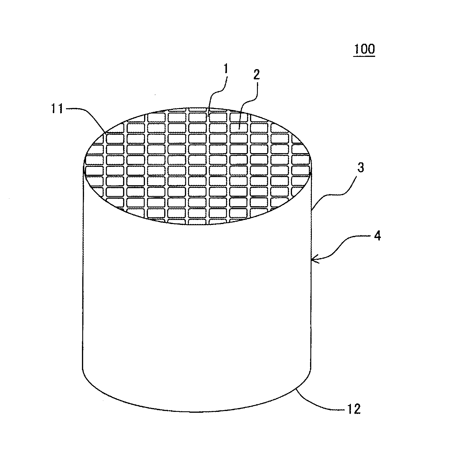
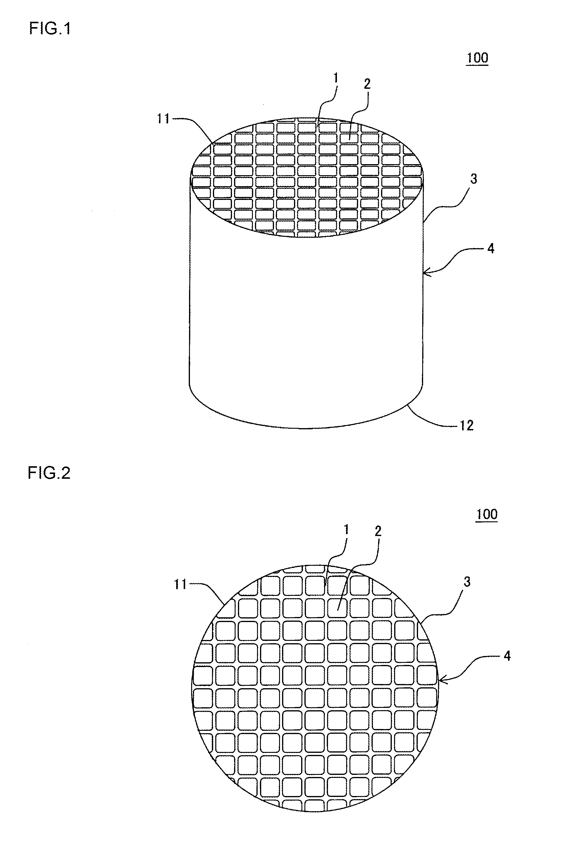
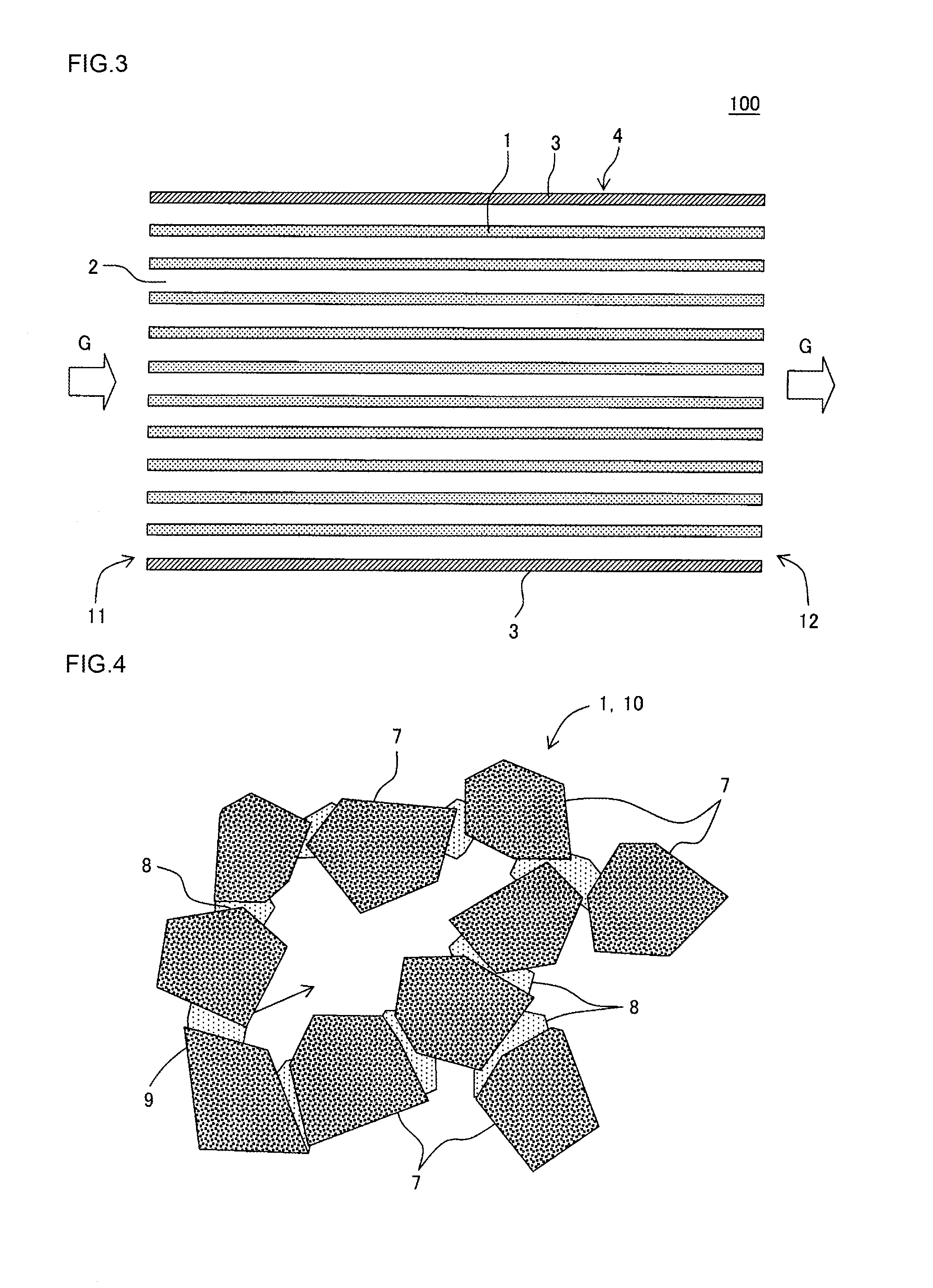
[0017]In a honeycomb structure of the present invention, partition walls of a honeycomb structure body are constituted of a porous body having aggregates and a bonding material to bond the aggregates to one another in a state where pores are formed among the aggregates. Furthermore, in this porous body, the aggregates include molten silica particles and the bonding material includes glass. In the honeycomb structure of the present invention, a content ratio of SiO2 in the porous body is 70 mass % or more and a thermal expansion coefficient of this porous body at 40 to 800° C. is from 1.5 to 6.0×10⁻⁶/° C. The honeycomb structure of the present invention is suitably usable as a catalyst support or a filter for use to purify an exhaust gas emitted from an internal combustion engine such as a diesel engine or each type of combustion device. In particular, the honeycomb structure

Problems solved by technology

Such a catalyst has a problem that it is difficult to inhibit the catalyst from peeling off from partition walls, even when such a technology to adjust an amount of the catalyst to be loaded, particle diameters of the catalyst and an open frontal area or fine pore volume of the partition w

Method used


Image

  • Honeycomb structure
  • Honeycomb structure
  • Honeycomb structure

Examples


example 1

[0067]In Example 1, first, a forming raw material was prepared by using molten silica particles, glass frit, and kaolin particles. As to blend ratios of the respective components in the forming raw material, the ratio of the molten silica particles was 50 mass %, the ratio of the glass frit was 30 mass %, and the ratio of the kaolin particles was 20 mass %. A median diameter of the molten silica particles was 15 μm, a median diameter of the glass frit was 10 μm, and a median diameter of the kaolin particles was 5 μm. As the glass frit, glass frit constituted of aluminosilicate glass was used. The glass frit used in Example 1 was “aluminosilicate glass A”. A column of “glass type” of Table 1 shows the type of glass frit used in preparing the forming raw material. Furthermore, a column of “clay” of Table 1 shows components other than the molten silica particles and glass frit used in preparing the forming raw material. In Example 1, the abovementioned kaolin particles corresponded to ...

example 2

[0081]In Example 2, a forming raw material was first prepared by using molten silica particles, glass frit and clay. As to blend ratios of the respective components in the forming raw material, the ratio of the molten silica particles was 50 mass %, the ratio of the glass frit was 30 mass %, and the ratio of the clay was 20 mass %. As the clay, Kibushi clay was used. In Example 2, the procedures of Example 1 were repeated except that the forming raw material was prepared as described above, to prepare a honeycomb structure of Example 2. As to the obtained honeycomb structure, “porosity (%)”, a “thermal expansion coefficient (×10−6 / ° C.)”, “A-axis compressive strength (MPa)” and a “median diameter (μm)” were measured in the same manner as in Example 1. Table 3 shows the measurement results. Furthermore, chemical components of the honeycomb structure of Example 2 were measured in the same manner as in Example 1. Table 3 shows the chemical components of the honeycomb structure of Examp...

example 3

[0082]The procedures of Example 1 were repeated except that as glass frit, “aluminosilicate glass B” of such a chemical composition as shown in Table 2 was used, to prepare a honeycomb structure of Example 3. As to the obtained honeycomb structure, “porosity (%)”, a “thermal expansion coefficient (×10−6 / ° C.)”, “A-axis compressive strength (MPa)” and a “median diameter (μm)” were measured in the same manner as in Example 1. Table 3 shows the measurement results. Furthermore, chemical components of the honeycomb structure of Example 3 were measured in the same manner as in Example 1. Table 3 shows the chemical components of the honeycomb structure of Example 3.


PUM


Abstract

There is disclosed a honeycomb structure. A honeycomb structure includes a pillar-shaped honeycomb structure body having partition walls defining a plurality of cells which become through channels for a fluid and extend from a first end face to a second end face, the partition walls are constituted of a porous body having aggregates and a bonding material to bond the aggregates to one another in a state where pores are formed among the aggregates, the aggregates include molten silica particles, the bonding material includes glass, a content ratio of SiO2 in the porous body is 70 mass % or more, and a thermal expansion coefficient of the porous body at 40 to 800° C. is from 1.5 to 6.0×10⁻⁶/° C.

Description

[0001]The present application is an application based on JP2014-63841 filed with Japan Patent Office on Mar. 26, 2014, the entire contents of which are incorporated herein by reference.BACKGROUND OF THE INVENTION[0002]1. Field of the Invention[0003]The present invention relates to a honeycomb structure, and more particularly, it relates to a honeycomb structure for use to purify an exhaust gas emitted from a diesel engine.[0004]2. Background Art[0005]A technology to purify an exhaust gas of a gasoline engine is based on an engine operated at a stoichiometric air-fuel ratio and a technology of a three-way catalyst to simultaneously purify HC, CO and NOx. On the other hand, a diesel engine is operated in oxygen excessive atmosphere, and hence the abovementioned three-way catalyst does not function and NOx cannot be reduced in oxygen excessive atmosphere.[0006]An example of a technology to reduce NOx in oxygen excessive atmosphere is a technology of selective catalytic reduction (SCR)....

Claims


Application Information

Patent Timeline
IPC IPC(8): B01J21/16B01J23/30F01N3/022B01J35/00B01D53/94B01D46/24B01J35/04B01J21/12
CPCB01J21/16B01J35/04B01J23/30F01N3/0222B01J35/0006B01D53/945B01D46/2418B01J21/12C04B35/14C04B38/0006C04B38/0074C04B38/0096C04B38/067C04B2235/3418C04B2235/36C04B2235/9607C04B35/62665C04B35/6316C04B2235/3201C04B2235/349C04B2235/5436C03C3/087C03C3/091C03C14/004C04B2111/00793C04B2111/0081Y10T428/24149C04B38/068B01D2255/20707B01D2255/20723B01D2255/20776B01D2255/2092B01D2255/30
Inventor ONO, MITSUHARUSATO, FUMIHARUUEDA, SHUJISUENOBU, HIROYUKI
Owner NGK INSULATORS LTD
Why Eureka
Try Eureka