
Large-caliber telescope non-linear interference detecting and filtering method

a large-caliber telescope and filtering method technology, applied in the direction of instruments, optical elements, optics, etc., can solve the problems of reduced tracking precision, unstable tracking speed, hydrostatic vibration, etc., to eliminate the effect of resonance, the largest influence on the tracking precision and performance of the telescope, and the effect of improving the performance of the telescop

Active Publication Date: 2015-10-01
NANJING INST OF ASTRONOMICAL OPTICS & TECH NAT ASTRONOMICAL OBSE
View PDF1 Cites 0 Cited by
  • Summary
  • Abstract
  • Description
  • Claims
  • Application Information

AI Technical Summary

Benefits of technology

The patent is about a method for detecting and filtering non-linear interference in a large-caliber telescope system. The method uses a computer software program to accurately measure the interference caused by the oil system used to control the telescope. The program uses a digital filter called a NOTCH to filter out the interference caused by the oil system. The program can adjust the filter's frequency band based on changes in the oil pad interfering frequency, ensuring accurate tracking performance. The method is flexible and simple to use, and it has been shown to improve the telescope's performance by eliminating interference from resonance in the system. The use of the NOTCH filter can also increase the rigidity of the closed loop system without affecting its stability. Overall, the method helps to improve the telescope's tracking performance and stability.

Problems solved by technology

Finally, it results in hydraulic vibration and it spreads to the whole telescope system via the outlet.
In the extra-low speed operation of the main shaft system of the large astronomical telescope, this non-linear interference of the oil pad vibration produces a fairly obvious impact, resulting in unstable tracking speed and reduced tracking precision.
However, the adjusted oil pad usually still produces some vibration, which in some cases directly results in failure of the telescope tracking precision to meet the specification.
However, this will increase the closed loop band width, making it more easily affected by interference, and also affecting the system stability.
A resonance type filter features good filtering characteristics at and close to its resonance point, and is suitable to pressure pulsation with constant frequency, therefore the filtering band width is narrow; the cavity filter is a low-pass filter, suitable in eliminating pulsation over the medium frequency, but not suitable to low frequency, as its structure will be excessively big when the filtering frequency is lowered; the resistive filter does not work to either flow pulsation or pressure pulsation, with big pressure loss, therefore its application is limited; a compound filter can produce a better filtering effect than a single one, but the pressure loss is high through multiple stages, and a big structure is required.
The disadvantages of using a pulsation attenuation device is: (a) hydraulic filters are expensive.
If the hydraulic pump speed varies over a large range, the oil pad vibration band will shift, this filter cannot work and another filter for the suitable bank must be used instead.
The impact from the hydraulic system to the telescope is transmitted to the telescope position feedback scale, so its position, speed and acceleration parameters include the oil pad vibration component, seriously affecting the precision of the telescope when tracking celestial bodies.
The disadvantage of a too wide NOTCH bandwidth is that the NOTCH band eliminating characteristic curve is not steep enough, with fairly high distortion of useful signal.
The disadvantage of a too narrow NOTCH bandwidth is: although the band eliminating characteristics are steep, it is possible that the whole narrow bank interference cannot be fully filtered.

Method used


Image

  • Large-caliber telescope non-linear interference detecting and filtering method
  • Large-caliber telescope non-linear interference detecting and filtering method
  • Large-caliber telescope non-linear interference detecting and filtering method

Examples


embodiment 1

Large-Caliber Telescope Non-Linear Interference Detecting and Filtering Method

[0036]In the following, embodiments of the invention are further described in conjunction with attached drawings and embodiment.

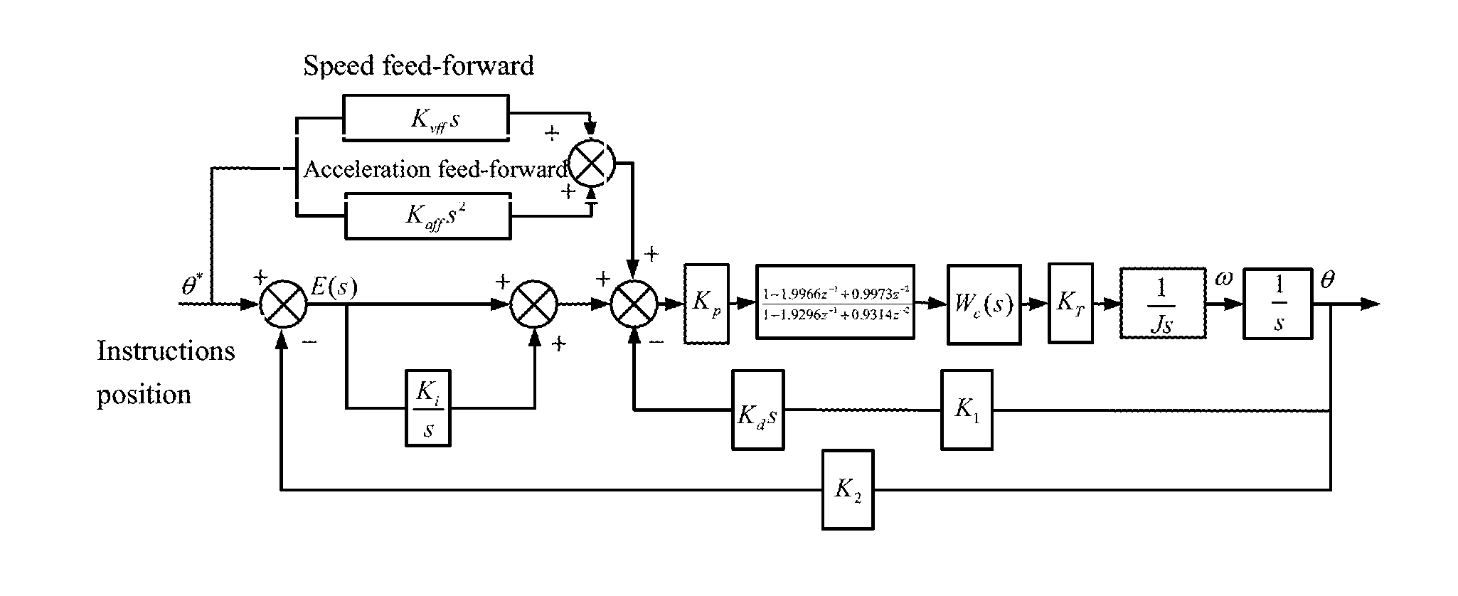
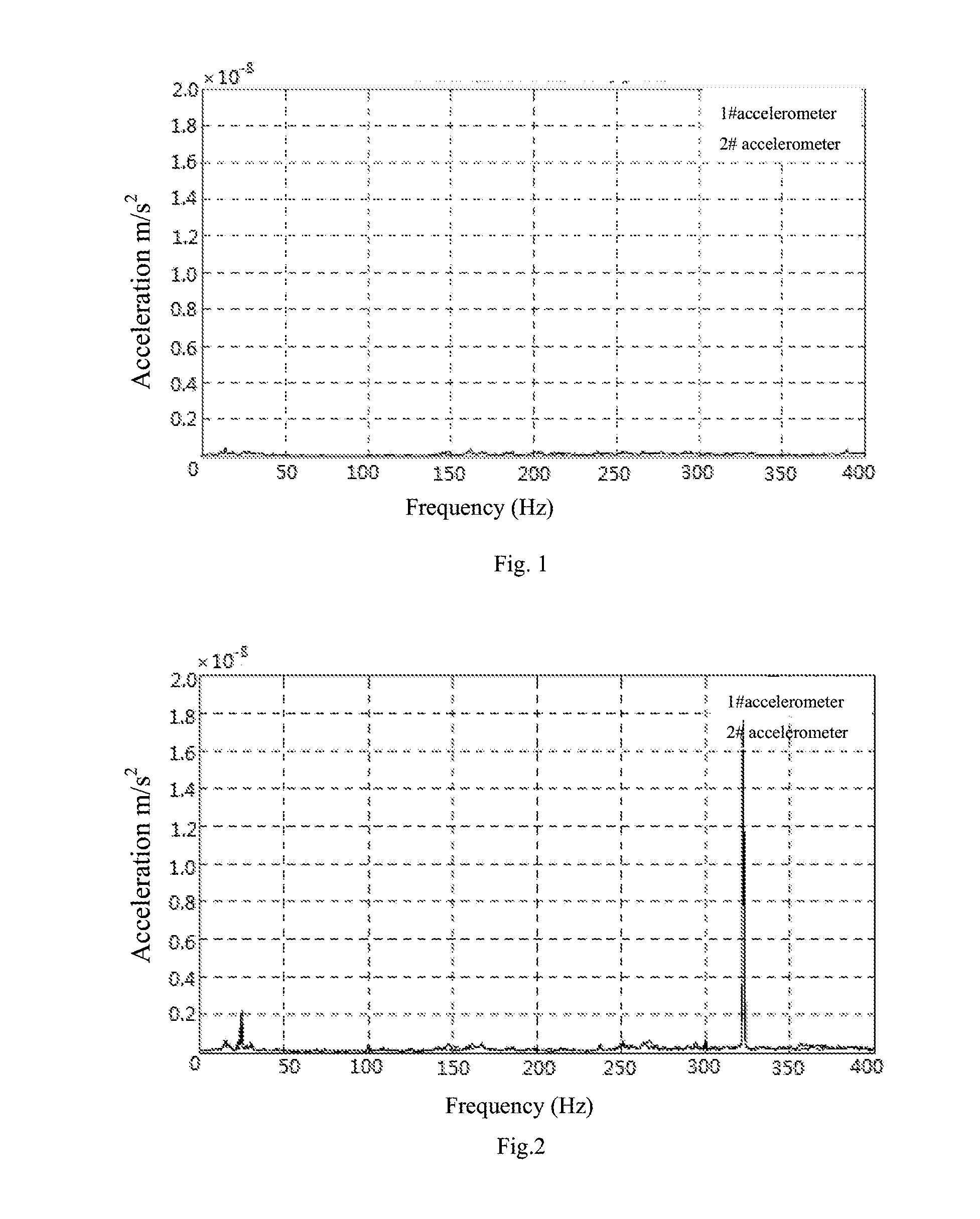
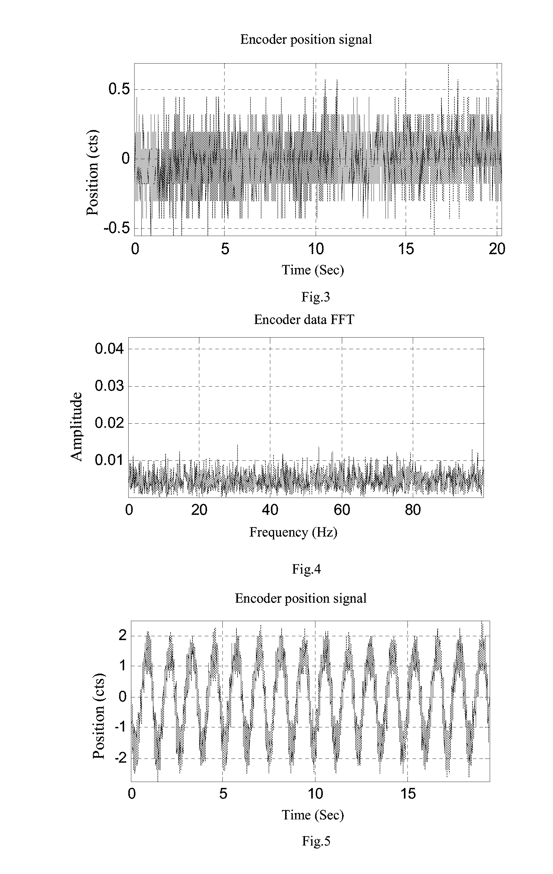
[0037]Two acceleration sensors are respectively set at the base of the telescope azimuth shaft and the gear oil diverter of the oil pad of a telescope with a caliber of 2.5 m. The signal of the accelerometer is input into the UMAC movement controller via the AD control card ACC-28E+OPT-1, and fed into the industrial personal computer via the Ethernet bus. When the oil pad is turned off and the telescope is static, the signals of the two accelerometers are measured and the acceleration vs frequency curve is plotted, as shown in FIG. 1. When the oil pad is turned on and the telescope is static, the signals of the two accelerometers are measured and the speed vs frequency curve is plotted, as shown in FIG. 2. It can be found by comparing the curves in the two diagrams that, after the...


PUM


Abstract

A large-caliber telescope non-linear interference detecting and filtering method is provided. The measure of the oil pad interference is accomplished with one of the following two methods, accelerometer and encoder, or using both of the said methods simultaneously. The filtering of the oil pad interference: set a NOTCH frequency as the main interfering frequency by using NOTCH filter to filter the interference and distinctly improve the telescope performance. The telescope and method is specific to a large-caliber telescope with an oil pad, by using an acceleration sensor and an encoder to precisely measure the non-linear interfering frequency of the telescope oil pad system, by using a NOTCH digital filter to accurately filter the interference due to the oil pad system, and through adjusting parameters of the digital filter to change the filter frequency band on the basis of the change of the oil pad interfering frequency.

Description

CROSS-REFERENCE TO RELATED APPLICATIONS[0001]This application claims priority to PCT Application No. PCT / CN2013 / 077909, having a filing date of Jun. 25, 2013, based on Chinese Application No. 201210244509.1 filed on Jul. 13, 2012, the entire contents of which are hereby incorporated by reference.FIELD OF TECHNOLOGY[0002]The following is about the interference detection and filtering for the control system of an astronomical telescope, specifically about the non-linear interference detecting and filtering method for a large-caliber telescope.BACKGROUND[0003]In most cases, static pressure bearings are used for the main shaft of a large-caliber astronomical telescope (especially azimuth shaft), hydraulic oil is injected between a pair of smooth surfaces, to form a pressure oil membrane to support the load, and also to lubricate the bearing surfaces. It has the advantages that the bearing lubricating surfaces feature high rigidity, long service life and low start power, able to carry ve...

Claims


Application Information

Patent Timeline
Patent Type & Authority Applications(United States)
IPC IPC(8): G01R35/00G02B23/00
CPCG02B23/00G01R35/00G02B23/16G02B27/646
Inventor YANG, SHIHAI
Owner NANJING INST OF ASTRONOMICAL OPTICS & TECH NAT ASTRONOMICAL OBSE
Learn More