High voltage electric device and electric compressor

Inactive Publication Date: 2015-10-15
DENSO CORP
View PDF15 Cites 12 Cited by
  • Summary
  • Abstract
  • Description
  • Claims
  • Application Information

AI Technical Summary

Benefits of technology

[0014]Accordingly, radiation performance of the heating components can be improved by the heat release insulating plate. As a r

Problems solved by technology

Thus, the technique has a problem with cool

Method used


Image

  • High voltage electric device and electric compressor
  • High voltage electric device and electric compressor
  • High voltage electric device and electric compressor

Examples


Example

First Embodiment

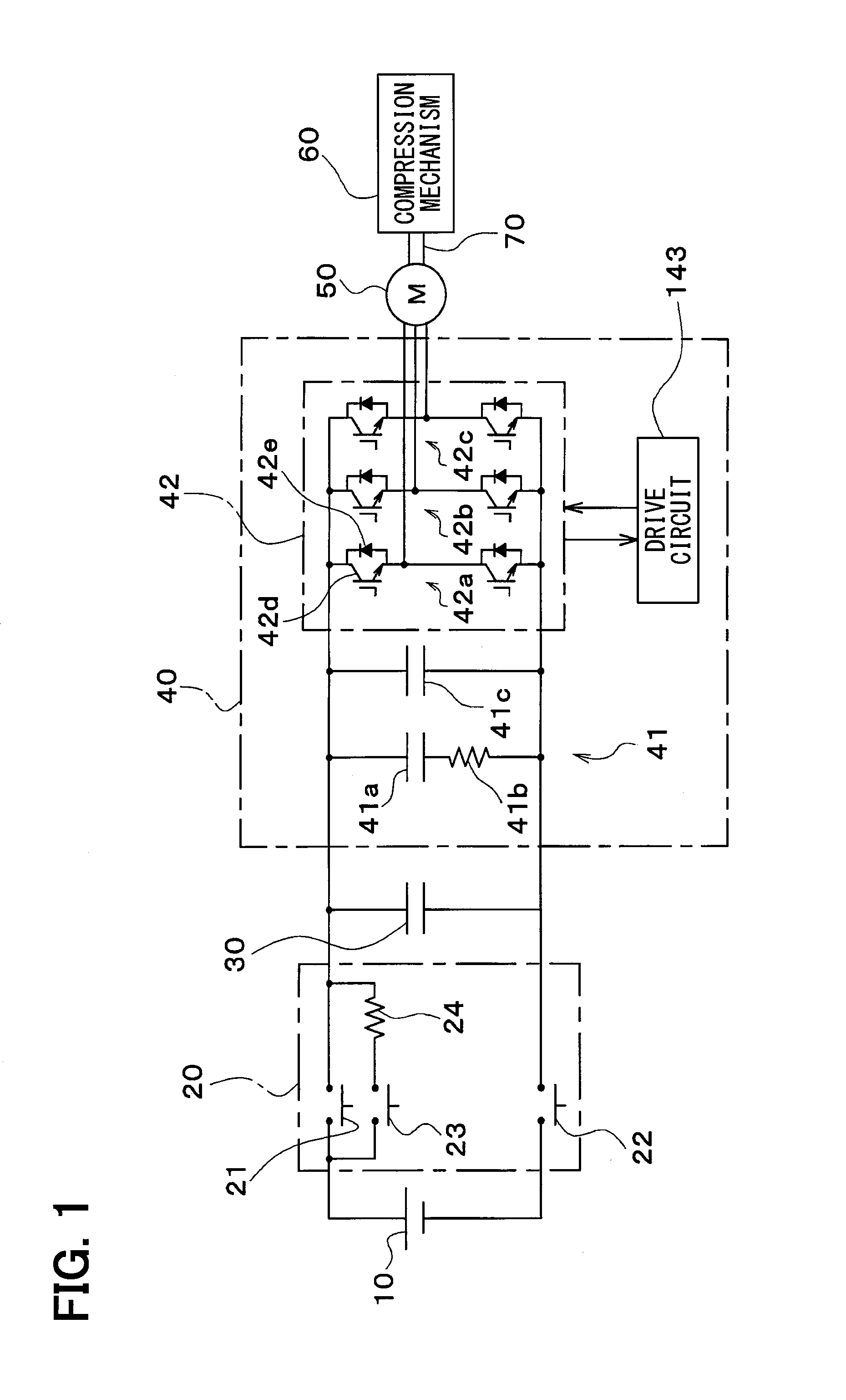
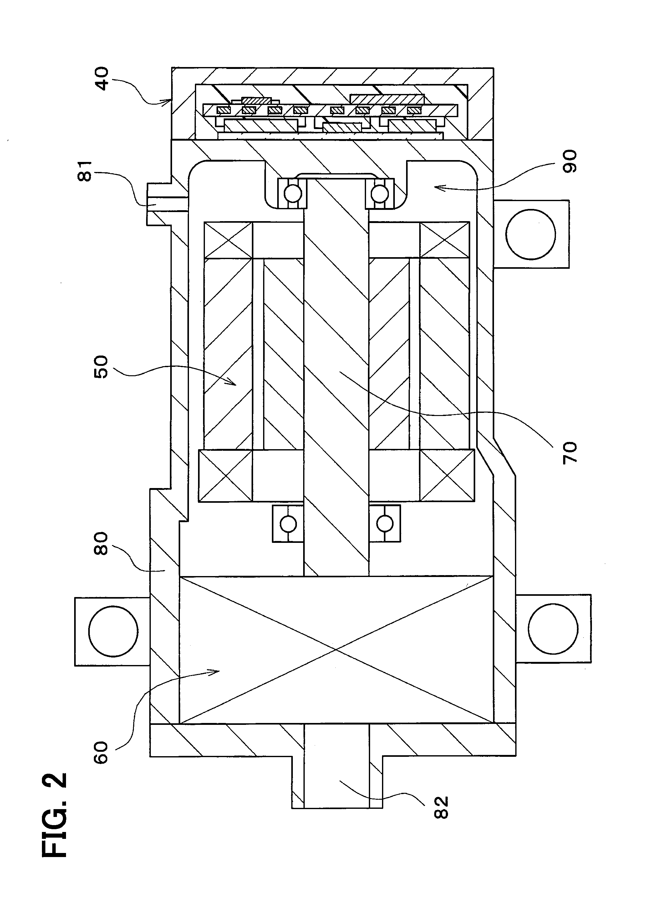
[0025]A first embodiment will be described below with reference to FIGS. 1 to 3. As illustrated in FIG. 1, a system having an electric compressor of the present embodiment includes a high-voltage battery 10, a high-voltage relay system 20, a smoothing capacitor 30, an inverter device 40, an electric motor 50, a compression mechanism 60, and a connecting mechanism 70.

[0026]The high-voltage battery 10 is a direct current power supply for driving the inverter device 40. The high-voltage relay system 20 has a function of preventing an inrush current from flowing through the inverter device 40 when applying a high voltage to the inverter device 40. Thus, the high-voltage relay system 20 includes a switch 21 connected to a positive electrode of the high-voltage battery 10, and a switch 22 connected to a negative electrode of the high-voltage battery 10. The high-voltage relay system 20 includes a switch 23 and a resistance 24. A series connection of the switch 23 and the r...

Example

Second Embodiment

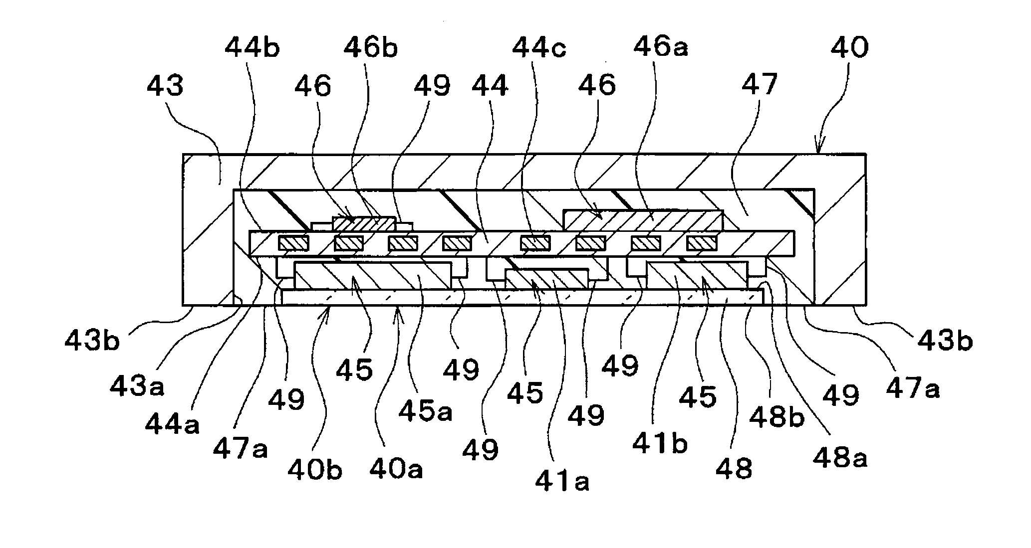
[0058]In the present embodiment, a part of the present disclosure that is different from the first embodiment will be described. In the present embodiment, as illustrated in FIG. 4, a case 43 is configured as a container having a hollow shape. The case 43 accommodates in its hollow portion an electric circuit board 44, heating components 45, electronic components 46, and a mold resin 47. In the present embodiment, an inverter device 40 is not provided with the heat release insulating plate 48. The resistance 41 b is omitted in FIG. 4.

[0059]The mold resin 47 seals the electric circuit board 44, the heating components 45, and the electronic components 46, and is also provided between the heating components 45 and the case 43 inside the case 43. As a consequence, the insulation between the heating components 45 and the case 43 is ensured. Grease and resin may be provided between the heating components 45 and the case 43 to ensure this insulation.

[0060]The case 43 is fi...

Example

Third Embodiment

[0063]In the present embodiment, a part of the present disclosure that is different from the second embodiment will be described. As illustrated in FIG. 5, a heat release insulating plate 48 is provided between an inner wall surface of a case 43 and heating components 45. Accordingly, the performance in cooling the heating components 45 can be improved.

[0064]When an outermost peripheral surface of a mold resin 47 and the heat release insulating plate 48 on a cooling unit 90-side is referred to as a reference surface 40b, in the present embodiment, the reference surface 40b is the same surface as an opposite surface 48b of the heat release insulating plate 48. The heating components 45 are respectively in contact with a contact surface 48a of the heat release insulating plate 48. Thus, the shortest distances of the heating components 45 from the reference surface 40b accord with each other.

[0065]In addition, the mold resin 47 and the heat release insulating plate 48 o...


PUM


Abstract

A high voltage electric device attached to a cooling unit includes heating components, an electric circuit board, a case, and an insulating member. The heating components are used at high voltage and are different in size. The heating components are fixed via lead wires respectively to the electric circuit board. The case accommodates the heating components and the electric circuit board. The insulating member seals the heating components and the electric circuit board in the case. An outermost peripheral surface of the insulating member on the cooling unit-side cooled by refrigerant is referred to as a reference surface. Respective shortest distances from the reference surface to the heating components are the same as each other. An electric compressor includes the high voltage electric device, an electric motor that is operated by electric power supplied by the high voltage electric device, and a compression mechanism that is driven by the electric motor and is applied to a refrigeration cycle. The cooling unit is cooled by the refrigerant drawn into the compression mechanism.

Description

CROSS REFERENCE TO RELATED APPLICATION[0001]This application is based on Japanese Patent Application No. 2012-248243 filed on Nov. 12, 2012, the disclosure of which is incorporated herein by reference.TECHNICAL FIELD[0002]The present disclosure relates to a high voltage electric device and an electric compressor.BACKGROUND ART[0003]In Patent Document 1, for example, there is conventionally proposed an inverter device including a smoothing capacitor provided on a power substrate. Specifically, the inverter device has such a configuration that: the power substrate is disposed in a box-shaped module case, and the module case is filled up with a resin mold layer from the power substrate to a position to cover at least the smoothing capacitor. Accordingly, the smoothing capacitor is fixed by the resin mold layer, so that vibration resistance of the smoothing capacitor improves.[0004]Prior Art Document[0005]Patent Document[0006]Patent Document 1: JP2010-74935A[0007]However, according to t...

Claims


Application Information

Patent Timeline
IPC IPC(8): F04D25/06H05K7/20
CPCF04D25/06H05K7/20263H05K7/20254H02K7/14H02M7/003H02K11/33
Inventor SAKAI, KOJI
Owner DENSO CORP
Why Eureka
Try Eureka