Laser waveguide device and laser waveguide system

a laser waveguide and laser waveguide technology, applied in the direction of instruments, optical radiation measurement, active medium materials, etc., can solve the problems of silver being deposited to increase loss, inability to use as a waveguide path for cosub>2 /sub>laser light, and low risk of end surface damage, etc., to achieve high energy output and simple structure

Active Publication Date: 2015-12-03
MORITA MFG CO LTD
View PDF1 Cites 11 Cited by
  • Summary
  • Abstract
  • Description
  • Claims
  • Application Information

AI Technical Summary

Benefits of technology

[0046]In one or more embodiments, the present invention provides a laser waveguide device and a laser waveguide system for monitoring, with a simple structure, the soundness of a laser waveguide path that guides invisible infrared laser light of a high energy output, so that the invisible infrared laser light is caused to exit safely.

Problems solved by technology

However, the fluoride-based optical fibers can merely guide infrared laser light having a wavelength of about 3 to 4 μm at the longest and thus cannot be used as a waveguide path for CO2 laser light.
The silver halide-based optical fibers and the chalcogenide-based optical fibers can guide infrared laser light having a longer wavelength but cannot guide visible laser light.
The silver halide-based optical fibers also have a problem of being sensitive to visible laser light having a short wavelength, resulting in silver being deposited to increase loss.
In the case of hollow optical fibers, the risk of end surface damage is lower than in the case of solid optical fibers, but it is required to consider the risk of breakage, which may be caused by bending, melting, contamination with foreign substances, or the like.
However, even in the case where the waveguide path of the infrared laser light is damaged, the visible laser light, which is guided by a waveguide path different from the waveguide path that guides the infrared light, normally exits.
Therefore, the soundness of the waveguide path that guides the infrared invisible light cannot be checked.
This complicates the system structure and makes it difficult to construct a low-cost system.
This may possibly cause electromagnetic hypersensitivity to the biological body.
However, in the case where laser light of a higher energy output is guided by the waveguide path, the waveguide path may be possibly broken by energy loss of the guided laser light itself.
It is not possible to monitor the soundness of the waveguide path in real time while laser light of a desired output level is caused to exit.
However, the guiding efficiency of a waveguide path for laser light is changed by, for example, a bending state of the waveguide path, and thus is not necessarily a constant value.
Since such adjustment increases troublesome work imposed on a user, it is difficult for the user to adjust the threshold value in accordance with the state of use.

Method used


Image

  • Laser waveguide device and laser waveguide system
  • Laser waveguide device and laser waveguide system
  • Laser waveguide device and laser waveguide system

Examples


Embodiment Construction

[0053]Embodiments of the present invention will be described with reference to the drawings.

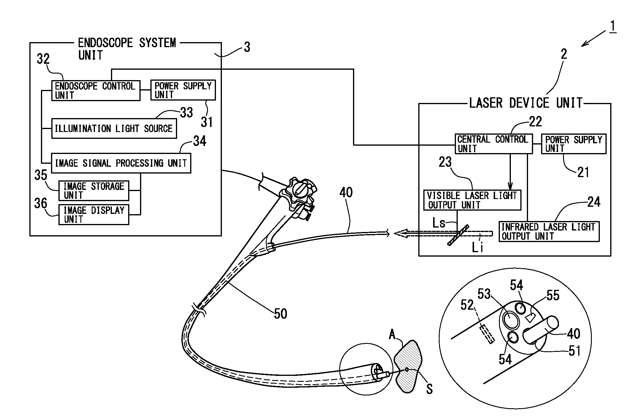
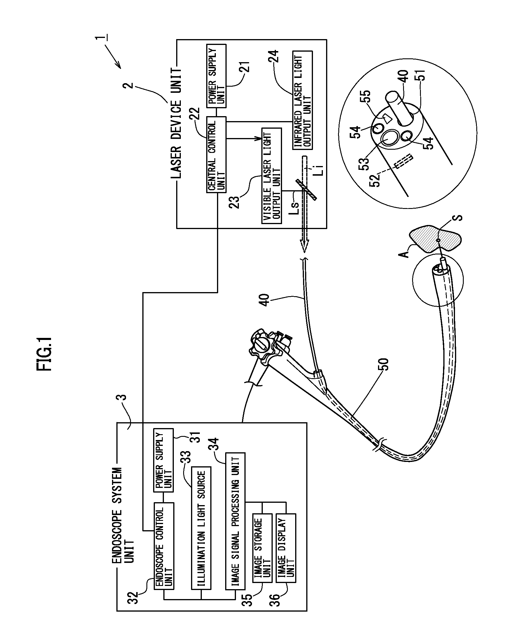
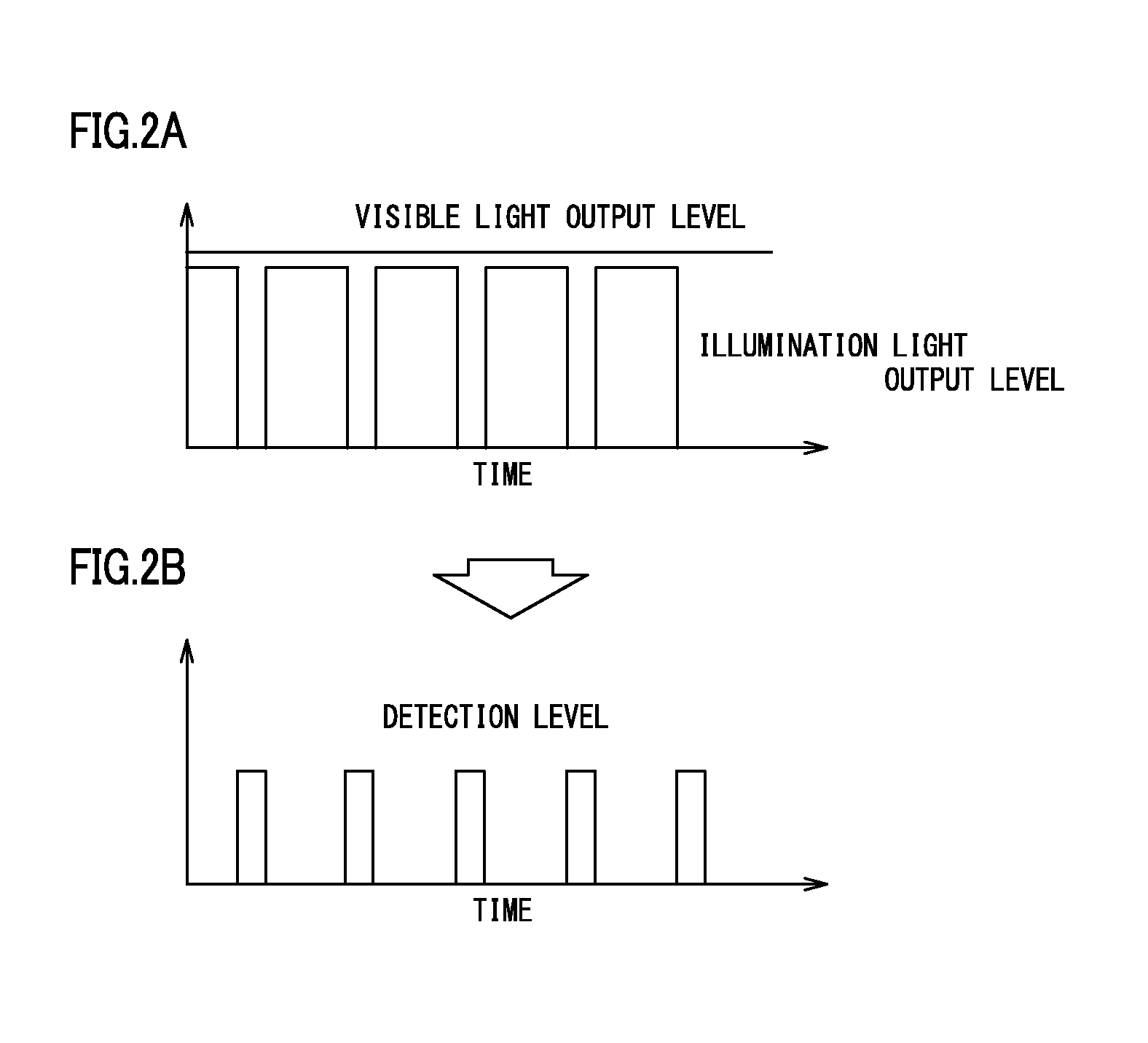
[0054]FIG. 1 is a schematic structural view of a laser light waveguide system 1 in an embodiment according to the present invention. FIGS. 2A and 2B show a method for detecting an output of visible laser light Ls. FIGS. 3A and 3B through FIG. 5 each show another method for detecting an output of the visible laser light Ls. FIG. 6 is a schematic structural view of a laser light waveguide system 1 in another embodiment according to the present invention.

[0055]The laser light waveguide system 1 includes a laser device unit 2, a laser light waveguide path 40, and an endoscope system unit 3.

[0056]The laser device unit 2 includes a power supply unit 21, a central control unit 22, a visible laser light provision unit 23 that oscillates and causes visible laser light Ls to exit, and infrared laser light provision unit 24 that oscillates and causes infrared laser light Li to exit. The visible laser li...


PUM


Abstract

A laser light waveguide device includes laser light provision units that oscillate and cause laser light to exit; a laser light waveguide path formed of an optical fiber capable of guiding the laser light; and a control unit that controls the laser light provision units. The control unit detects an illumination spot (output of the visible laser light) based on a captured image, captured by an image capturing unit, of a laser light illumination area and an area close thereto illuminated with the laser light, and controls exit of the infrared laser light by the infrared laser light provision unit based on a result of detection of the illumination spot (output of the visible laser light).

Description

TECHNICAL FIELD[0001]The present invention relates to a laser waveguide device and a laser waveguide system for guiding infrared laser light usable in, for example, medical and industrial fields.BACKGROUND ART[0002]Infrared laser light, which has a high energy output and is absorbed much into water, is useful for industrial laser processing devices and also for medical laser scalpels. Especially, devices using infrared laser light such as Er-YAG laser light oscillating at a wavelength of 2.94 μm, CO2 laser light oscillating at a wavelength of 10.6 μm, or the like are used as products in medical and industrial fields.[0003]In the industrial fields, such infrared laser light is used for cutting various materials, welding, and surface modification. In the medical field, such infrared laser light is used for the purpose of incision, coagulation, transpiration, hemostasis and the like of biological tissues. Infrared laser light used in these fields has a significantly high energy output ...

Claims


Application Information

Patent Timeline
Patent Type & Authority Applications(United States)
IPC IPC(8): H01S3/00G01J1/04A61B1/06H01S3/23H01S3/223A61B18/24G01J1/02H01S3/16
CPCH01S3/0071G01J1/0233G01J1/0425H01S3/1608H01S3/1698A61B2018/2261H01S3/23H01S3/2232A61B18/24A61B1/0653G01J2001/0257H01S3/1643G01J1/4257A61B2018/00166A61B2018/00642A61B2018/00672A61B2018/00702A61B2018/00708A61B2018/00982A61B1/0655
Inventor HONGO, AKIHITOHIYOSHI, KATSUMIWADA, MASATO
Owner MORITA MFG CO LTD
Why Eureka
Try Eureka