
Barrier layer for corrosion protection in electrochemical devices

a barrier layer and electrochemical technology, applied in the field of electrochemical and fuel cells, can solve the problems of cell not working anymore, sublayers subject to corrosion, and even more damage to the anode side of the mea, and achieve the effect of improving stability and corrosion protection

Active Publication Date: 2015-12-10
GREENERITY GMBH
View PDF7 Cites 9 Cited by
  • Summary
  • Abstract
  • Description
  • Claims
  • Application Information

AI Technical Summary

Benefits of technology

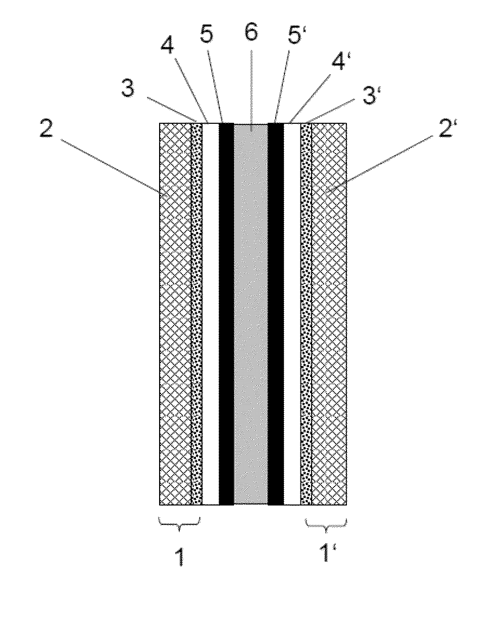
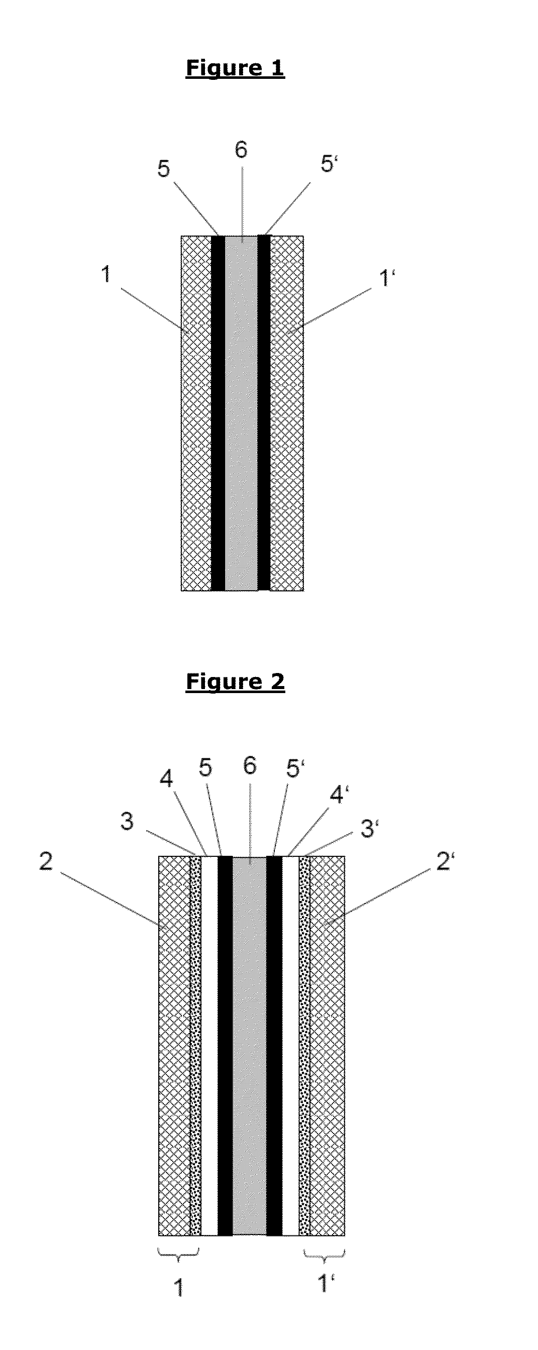
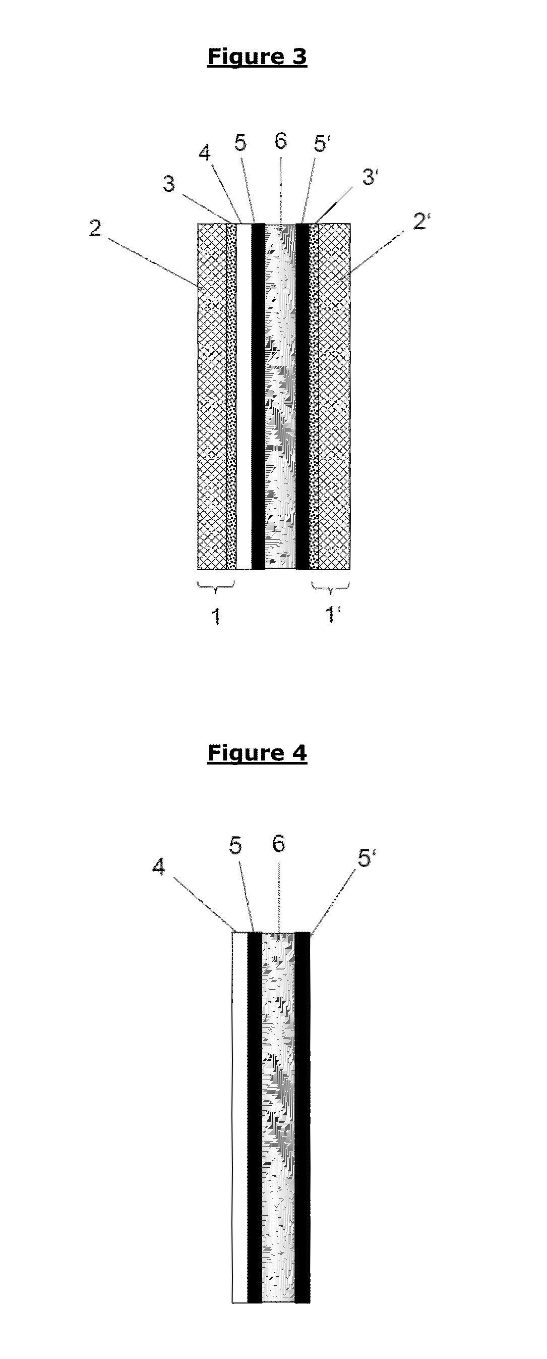
This patent describes a barrier layer for protecting carbon-based gas diffusion layers in electrochemical devices from corrosion. The barrier layer is made of an electrically conductive ceramic material and a non-ionomeric polymer binder. It can be applied to the cathode or anode side of the device, and its use results in improved stability and performance at high cell potential events. Compared to other materials, the barrier layer is permanent and can effectively protect both the cathode and anode sides of the device.

Problems solved by technology

It should be noted that the material / layer of WO2011 / 076396 does not provide for dissipation of current under a cell reversal event, which potentially makes the event even more damaging for the anode side of the MEA.
Under a cell reversal tolerance event, such carbon sublayer would be subject to corrosion and the cell would not work any more.

Method used


Image

  • Barrier layer for corrosion protection in electrochemical devices
  • Barrier layer for corrosion protection in electrochemical devices
  • Barrier layer for corrosion protection in electrochemical devices

Examples


example 1

Preparation of Catalyst-Coated Membranes (CCM)

[0147]A catalyst-coated membrane (“CCM”) is provided having an anode catalyst loading of 0.1 mg Pt / cm2 (based on Pt / C-catalyst Elyst® 20Pt 0350 from Umicore AG & Co KG, Hanau, Germany) and a cathode platinum loading of 0.5 mg Pt / cm2, based on Pt black (Umicore AG & Co KG, Hanau, Germany) mixed with IrO2 / TiO2 catalyst Elyst Ir75 0480 (Umicore AG & Co KG) in a ratio of 30:70 applied on both sides of an ionomer membrane Nafion® 212CS (thickness 50.8 μm, DuPont, USA). The catalyst layers are applied by standard decal methods. The active area of both catalyst layers is 71 mm×71 mm and the overall membrane size is 110 mm×110 mm.

example 2

Preparation of a GDL with Barrier Layer (BL)

[0148]To a water-based PTFE dispersion TF 5032Z (Dyneon GmbH, Burgkirchen, Germany), containing 55.2 wt.-% PTFE with average particle size of 160 nm and 3.8 wt.-% emulsifier, solvent dipropylene glycol (Merck Cat. No. 803265) is added to obtain a dispersion with the following composition (wt.-%):

PTFE (solid polymer)9.0wt.-%DI Water:6.7wt.-%Emulsifier:0.6wt.-%Dipropylene glycol:83.7wt.-%Total100.0wt.-%

[0149]The dispersion is then stirred for 30 minutes. Thereafter, 30.0 grams of a supported conductive metal oxide IrO2 / TiO2 (Elyst® Ir75 0480; Umicore AG & Co KG) is then added to 70.0 grams of the PTFE dispersion prepared above and the mixture is thoroughly dispersed in a bead mill (grinding media zirconia, ca. 1 mm diameter, milling time 30 minutes at about 2.000 rpm). The resulting barrier layer ink contains 30.0 wt.-% IrO2 / TiO2 oxide material and 6.3 wt.-% PTFE. This results in a ratio of Ir oxide material / PTFE=4.76:1, i.e. a binder conten...


PUM

PropertyMeasurementUnit
Thicknessaaaaaaaaaa
Electrical conductivityaaaaaaaaaa

Abstract

The invention is directed to a barrier layer for corrosion protection in electrochemical devices, e.g. carbon based gas diffusion layers (GDLs) in electrochemical devices, comprising electrically conductive ceramic material and a non-ionomeric polymer binder. The electrically conductive ceramic material has an electrical conductivity of >0.1 S / cm, preferably >1 S / cm in air atmosphere (as detected by the powder method) and is selected from the group of precious metal and / or base metal containing oxides, carbides, nitrides, borides and mixtures and combinations thereof. Membrane-electrode assemblies (MEAs), catalyst-coated membranes (CCMs), gas diffusion electrodes (GDEs) and gas diffusion layers (GDLs) comprising the barrier layer of the invention show improved corrosion resistance, preferably against carbon corrosion; particularly in start-up / shut-down cycles and fuel starvation situations of PEM fuel cells.

Description

FIELD OF INVENTION[0001]The present invention is directed to the field of electrochemistry and fuel cells. This invention provides a barrier layer for corrosion protection in electrochemical devices, e.g. for carbon-based gas diffusion layers (GDLs) or current collectors, in electrochemical devices such as polymer electrolyte fuel cells (“PEMFC”) or PEM electrolyzer cells. The barrier layer of the present invention finds use in PEMFC components such as membrane electrode assemblies (“MEAs”), catalyst-coated membranes (“CCMs”), gas diffusion electrodes (“GDEs”) and gas diffusion layers (“GDLs”). More specifically, the barrier layer disclosed in the present invention provides improved resistance to carbon corrosion of carbon-based GDLs and leads to a better stability in start-up / shut down cycles and fuel starvation situations in PEMFC.BACKGROUND OF THE INVENTION[0002]Fuel cells (FCs) are power generating electrochemical devices used or commercially foreseen to be used for a wide range...

Claims


Application Information

Patent Timeline
IPC IPC(8): C25B11/04H01M8/10
CPCC25B11/0442H01M2300/0082H01M2008/1095H01M8/1002H01M4/8605H01M4/8615H01M4/8657H01M8/0234H01M8/0245Y02E60/50C25B9/23C25B11/031C25B11/051C25B11/073
Inventor SUCHSLAND, JENS-PETERGHIELMI, ALESSANDROBRAUN, PIA
Owner GREENERITY GMBH
Learn More