Electronic temperature sensor for measuring the junction temperature of an electronic power switch during operation, and method for measuring the temperature of the junction by this electronic sensor

a technology of electronic power switch and electronic temperature sensor, which is applied in the direction of electronic commutators, dynamo-electric converter control, instruments, etc., can solve the problems of restricting the use of thermocouples to thermal equilibrium conditions, unusable normally, and affecting the operation of the electronic power switch, so as to reduce the parasitic current

Active Publication Date: 2015-12-31
SAFRAN VENTILATION SYST +2
View PDF5 Cites 22 Cited by
  • Summary
  • Abstract
  • Description
  • Claims
  • Application Information

AI Technical Summary

Benefits of technology

[0058]in a first step, preparing the temperature measurement of the power junction of the tested switch, by commanding the switch to measure the temperature, in the open state in the on state, and blocking the remaining switches so as to cancel or minimize the parasitic

Problems solved by technology

However, although operational solutions exist for the electrical isolation of these thermocouple, electrically conductive sensors, the response time for this type of temperature sensor, i.e., the time resolution of thermocouple sensors, remains at around ten milliseconds, which restricts the use of thermocouples to thermal equilibrium conditions.
However, these heat radiation detectors require a field of view on the measured object with no concealed portions, which is not ordinarily possible on power modules.
Indeed, the traditional encapsulation techniques do not generally make it possible to have unhindered visibility of the module, and this type of detector cannot be integrated into a component housing.
One of the difficulties of this indirect elec

Method used


Image

  • Electronic temperature sensor for measuring the junction temperature of an electronic power switch during operation, and method for measuring the temperature of the junction by this electronic sensor
  • Electronic temperature sensor for measuring the junction temperature of an electronic power switch during operation, and method for measuring the temperature of the junction by this electronic sensor
  • Electronic temperature sensor for measuring the junction temperature of an electronic power switch during operation, and method for measuring the temperature of the junction by this electronic sensor

Examples


Embodiment Construction

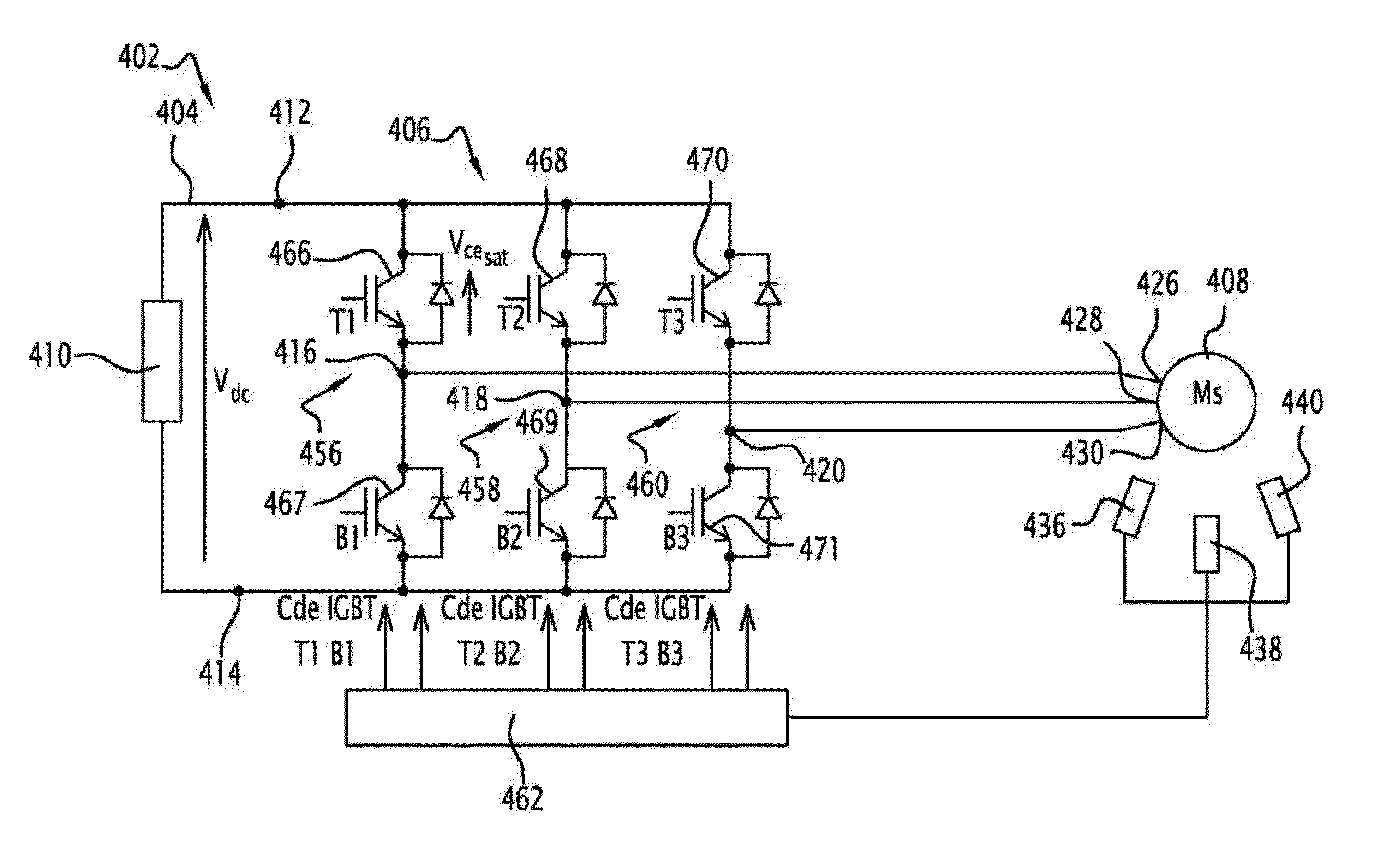
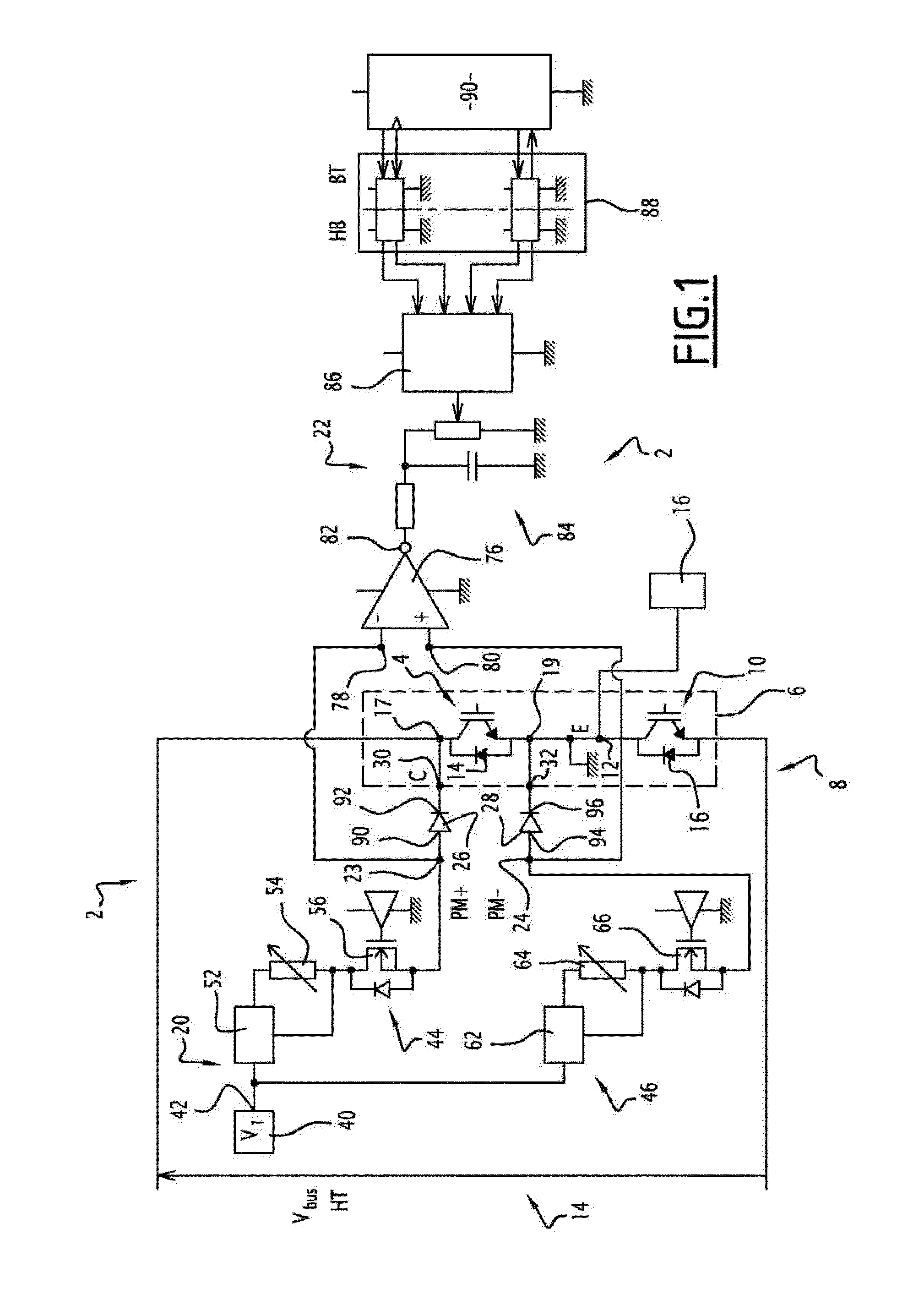
[0071]According to FIG. 1, an electronic temperature sensor 2 according to the invention is configured to measure and monitor the junction temperature of a controlled electronic power switch 4 of an electronic switching cell 6 of a static converter 8.

[0072]Here, a single switching cell 6 is shown, the static converter being able to have several.

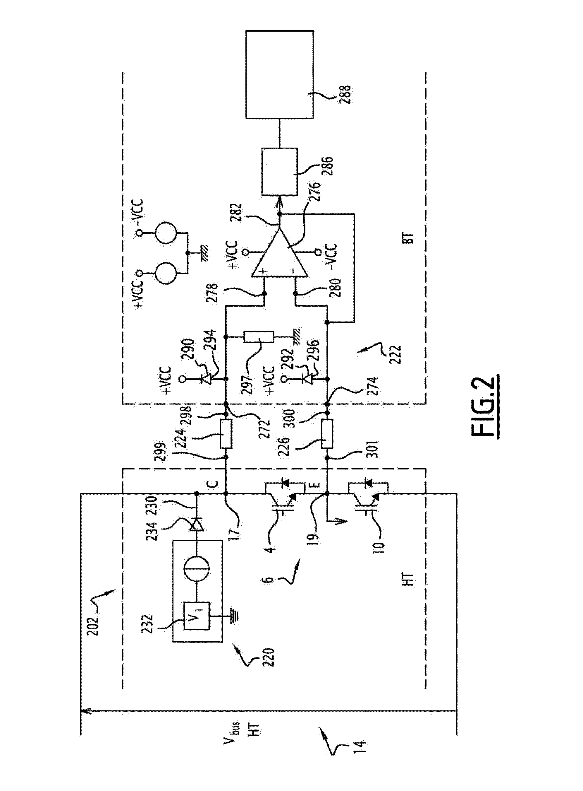
[0073]The switching cell 6 comprises, as first switch, the electronic power switch 4, and a second controlled electronic switch 10, the first and second controlled electronic switches 4, 10 being connected to one another in series by a midpoint 12.

[0074]The first and second switches 4, 10 each comprise a unique and different free-wheeling diode 14, 16 mounted in antiparallel.

[0075]The series circuit 6 thus formed is connected between a voltage source or bus, here the source 14 shown by the voltage Vbus, and connected to a current source 16 forming a charge through the midpoint 12.

[0076]The first and second electronic switches 4, 10 are a prio...


PUM


Abstract

An electronic temperature sensor for measuring the junction temperature of an electronic power switch (4) of a static converter (8) includes an injection source of a calibrated measurement current (20) and a differential voltage measurement amplifier (76; 276). The electronic temperature sensor includes a first series connection (26) element and a second series connection (28) connected respectively to the inlet terminals (78, 80) of the differential voltage amplifier (76; 276). The first and second series connection elements (26, 28; 224, 226) are configured to protect the amplifier against a high voltage, have essentially identical electrical characteristics and are included in the set formed by resistances and high-voltage (HV) rapid diodes.

Description

FIELD OF THE INVENTION[0001]The present invention relates to an electronic temperature sensor designed to measure the junction temperature of an electronic power switch during operation and a method for measuring the temperature of the junction using the electronic sensor with a short response time.[0002]Direct temperature measurements of controlled electronic switches, integrated into static converters, themselves integrated into electrical power systems, are delicate because they are very intrusive due to the small size of those encapsulated components involving high voltages.BACKGROUND OF THE INVENTION[0003]The use of thermocouple or heat-sensitive sensors in general as temperature sensors in such electrical systems is known.[0004]However, although operational solutions exist for the electrical isolation of these thermocouple, electrically conductive sensors, the response time for this type of temperature sensor, i.e., the time resolution of thermocouple sensors, remains at aroun...

Claims


Application Information

Patent Timeline
IPC IPC(8): G01K13/00H02P27/06H02M7/537
CPCH02M2001/327G01K7/01G01K2217/00G01K13/00H02M7/537H02P27/06H02M1/327
Inventor ROLLIN, PASCALRICHARDEAU, FREDERICMORVAN, MATTHIEUMOSSER, FRANCK
Owner SAFRAN VENTILATION SYST
Why Eureka
Try Eureka