Method for Forming Aluminide Coating Film on Base Material

a technology of aluminide coating and base material, applied in the direction of solid-state diffusion coating, climate sustainability, machine/engine, etc., can solve the problems of oxidation erosion, layer degradation, and brought about, and achieve the effects of improving workability, high efficiency and sound, and sa

Inactive Publication Date: 2016-01-28
HITACHI LTD
View PDF2 Cites 11 Cited by
  • Summary
  • Abstract
  • Description
  • Claims
  • Application Information

AI Technical Summary

Benefits of technology

[0042]According to the present invention, it is possible to provide a method for forming an aluminide coating, in that a metal aluminum film or an aluminum based alloy film can be electroplated, in a safe, high efficient and sound manner, topically to a selective area of a heat resistant superalloy substrate for use in a high temperature member and the like. Consequently, there can be provided a method for forming an aluminide coating having an easier handling and a better workability than that in the related art. The method for forming an aluminide coating of the invention is suitable for repairing a heat resistant member. In addition, by using the method for forming an aluminide coating of the invention, there can be provided a heat resistant member which is low in production cost and high in reliability.

Problems solved by technology

Even in a turbine blade provided with a thermal barrier coating, when it is used for some period of time in a high temperature gas environment of a gas turbine, oxidation erosion due to attack by the high temperature gas and corrosion due to chemical reactions with contaminants in the combustion product are brought about.
As a result, the coating layer is gradually degraded, and causes damages such as wear and fracture.
Thus damaged thermal barrier coating layer requires to be repaired, but simple reconstruction of only the worn-out part of the coating layer causes an insufficient adhesion.
In most cases, the damage to be repaired is generated only in a part of the coating layer, and therefore, for repairing a part of the coating layer, the removal and reconstruction of all the coating layers including the aluminide coating bring a large loss of time and cost.

Method used


Image

  • Method for Forming Aluminide Coating Film on Base Material
  • Method for Forming Aluminide Coating Film on Base Material
  • Method for Forming Aluminide Coating Film on Base Material

Examples


example 1

Preparation and Evaluation of Example 1

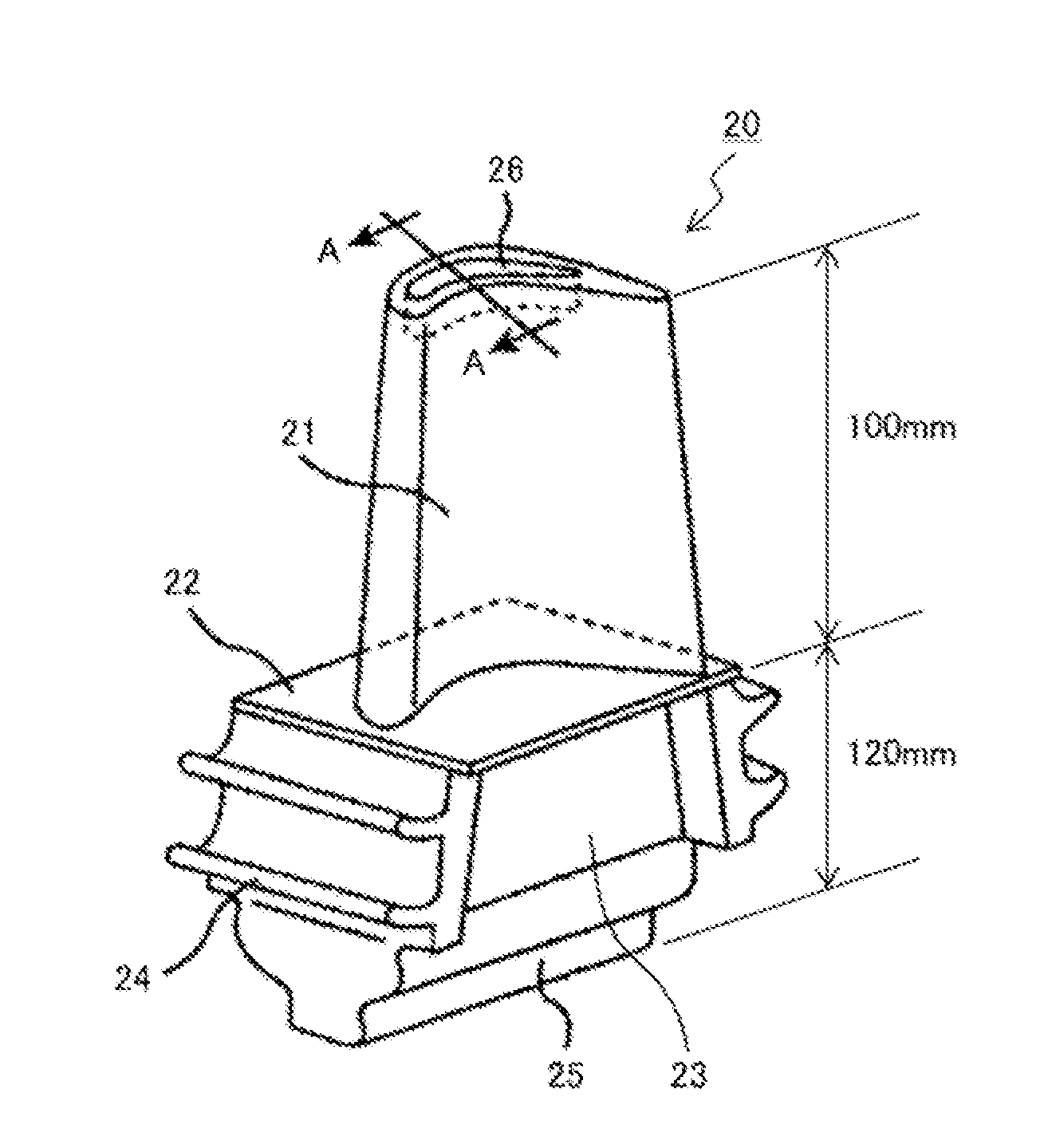
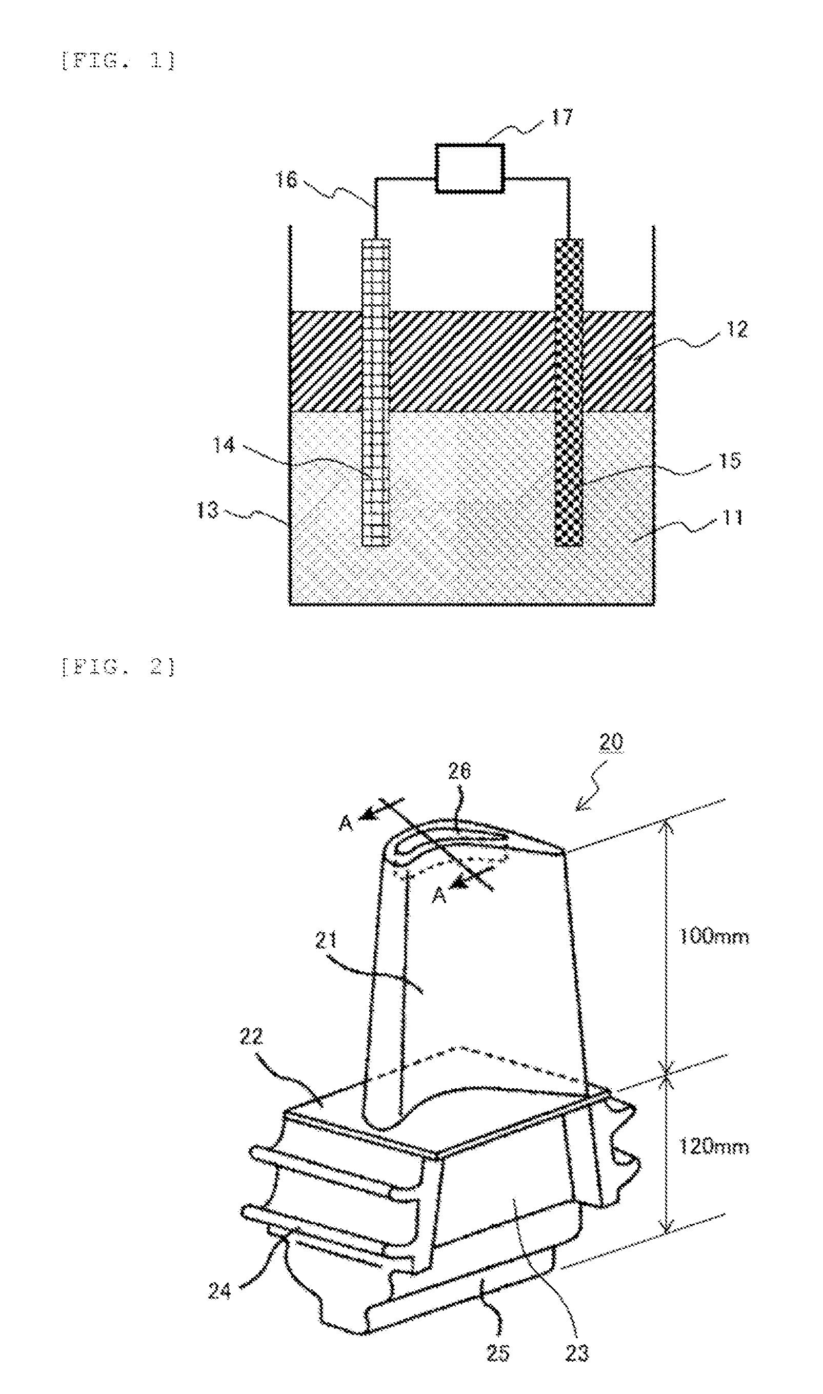
[0064]FIG. 2 is a schematic drawing showing a perspective view of an example of a heat resistant member (turbine blade) according to the present invention. A turbine blade 20 shown in FIG. 2 is a heat resistant member used as, for example, a rotor blade in a first stage of a gas turbine including three stages of rotor blades. The turbine blade 20 includes a blade portion 21, a platform portion 22, a shank portion 23, seal fins 24, and a dovetail 25, and is mounted to a rotor disk (not shown) via the dovetail 25. The blade portion 21 is provided with a tip pocket 26 at a tip portion thereof. Meanwhile, in the rotor blade, there is provided a cooling hole (not shown) which allows a coolant (for example, air or water steam) to pass through and cool the rotor blade from inside so as to penetrate from the dovetail to the blade portion.

[0065]As an example of the size of the turbine blade 20, the length from the platform portion 22 to the tip of the b...

example 2

Preparation and Evaluation of Example 2

[0090]Hereinafter, a partial repair of a thermal barrier coating layer will be explained with reference to FIG. 6. FIGS. 6(a) to 6(e) are schematic drawings showing cross sectional views of exemplary steps in a partial repair of a thermal barrier coating layer formed on a superalloy substrate.

[0091]A gas turbine was operated for a predetermined period of time using the turbine blade 20 produced in Example 1 above, and thereafter, the blade portion 21 of the turbine blade 20 was inspected. As a result, a damage portion 61 due to corrosion or oxidative erosion was confirmed on the surface (thermal barrier coating layer) of the blade portion 21 (see FIG. 6 (a)).

[0092]Firstly, a step was performed in which corrosion products / oxidation products 62 and a degraded thermal barrier coating layer (a heat resistant alloy layer 32 and a ceramic thermal barrier layer 33) were removed in the damaged portion 61 of the thermal barrier coating layer to expose a...

example 3

Preparation and Evaluation of Example 3

[0099]In Example 3, a simultaneous partial repair of plural portions of a thermal barrier coating layer was conducted by a method as shown in FIG. 7 with the same non-aqueous plating liquid as in Example 2. FIGS. 7(a) to 7(d) are schematic drawings showing cross sectional views of other exemplary steps in a partial repair of a thermal barrier coating layer formed on a superalloy substrate. Firstly, a step of exposing a base metal of the substrate was carried out for the plural damaged portions 61 in the same manner as in Example 2 to obtain clean base metal-exposed portions 63 (see FIGS. 7(a) and 7(b)).

[0100]A topical plating bath 70′ (provided with a plating tank 13″ which included a top cover 71′ capable of being slidably opened and closed and which was filled with a non-aqueous plating liquid 11, and a counter electrode 15 fixed inside the plating tank 13″) was prepared. Then, in the same manner as in Example 2, the topical plating bath 70′ ...


PUM

PropertyMeasurementUnit
temperatureaaaaaaaaaa
molar ratioaaaaaaaaaa

Abstract

There is provided a method for forming an aluminide coating on a surface of a heat resistant superalloy substrate, comprising the steps of: exposing a base metal of the substrate in a selective area; forming a aluminum or an aluminum alloy film on the exposed base metal, by a non-aqueous electroplating; and conducting a heat treatment to the substrate on which the film is formed, in order to make a diffusion reaction between an aluminum component in the film and the base metal, and form the aluminide coating, wherein: there is used, as a plating liquid, a non-aqueous plating liquid containing a halide of the metal to be plated and an organic compound which forms an ion pair with the metal halide; and the electroplating is conducted by immersing the selective area into the plating liquid through the use of predetermined means for shielding the plating liquid from the atmosphere.

Description

TECHNICAL FIELD OF THE INVENTION[0001]The present invention relates to a technique of forming an aluminide coating on a base material (substrate), and in particular to a method for forming an aluminide coating on a selective area of a high temperature member comprising a heat resistant superalloy.DESCRIPTION OF BACKGROUND ART[0002]In high temperature members (for example, a turbine blade and a combustor of a gas turbine, and the like) exposed to high temperature combustion gas, heat resistant superalloys (for example, a nickel based superalloy or a cobalt based superalloy) having excellent high temperature strength are used as a substrate thereof. Such a high temperature member is usually provided with a thermal barrier coating (TBC) on the surface thereof in order to enhance oxidation resistance and corrosion resistance at a high temperature. Typically, an aluminide coating or a heat resistant alloy layer (for example, MCrAlY alloy layer) is formed directly on the heat resistant su...

Claims


Application Information

Patent Timeline
Patent Type & Authority Applications(United States)
IPC IPC(8): C23C10/04B32B15/01C21D6/00C22F1/10C22F1/18C25D3/44C25D5/02C25D5/50C25D7/00F01D5/28
CPCC23C10/04C25D3/44C25D5/50C25D7/00C25D5/022F05D2300/173C22F1/18C21D6/00B32B15/012B32B15/017F01D5/288C22F1/10C23C10/28C25D21/11F05D2230/31C25D3/665C25D5/02C25D5/34C25D17/02Y02T50/60
Inventor NAKANO, HIROSHINEGISHI, YOSHINORIAKAHOSHI, HARUOIZUMI, TAKESHIKOJIMA, YOSHITAKAARIKAWA, HIDEYUKI
Owner HITACHI LTD
Why Eureka
Try Eureka