
Lead-acid battery separators with ultra low resistivity and sustained wettability

a technology of lead-acid battery separator and resistivity, which is applied in the direction of sustainable manufacturing/processing, batteries, cell components, etc., can solve the problems of inability to be easily washed away, and achieve the effect of sustained wettability and high porosity

Active Publication Date: 2016-01-28
AMTEK RES INT
View PDF4 Cites 14 Cited by
  • Summary
  • Abstract
  • Description
  • Claims
  • Application Information

AI Technical Summary

Benefits of technology

This patent describes a separator used in batteries. The separator is made up of a strong matrix of polyethylene, which is reinforced by adding precipitated silica to make it easier for the battery to release the electric current. The polyethylene is also mixed with plasticizer to protect it from oxidation. Surfactants are added to help dissolve the plasticizer and make sure it spreads evenly. This mixture of materials creates a separator that is resistant to shrinking and deformation during battery charging and discharging.

Problems solved by technology

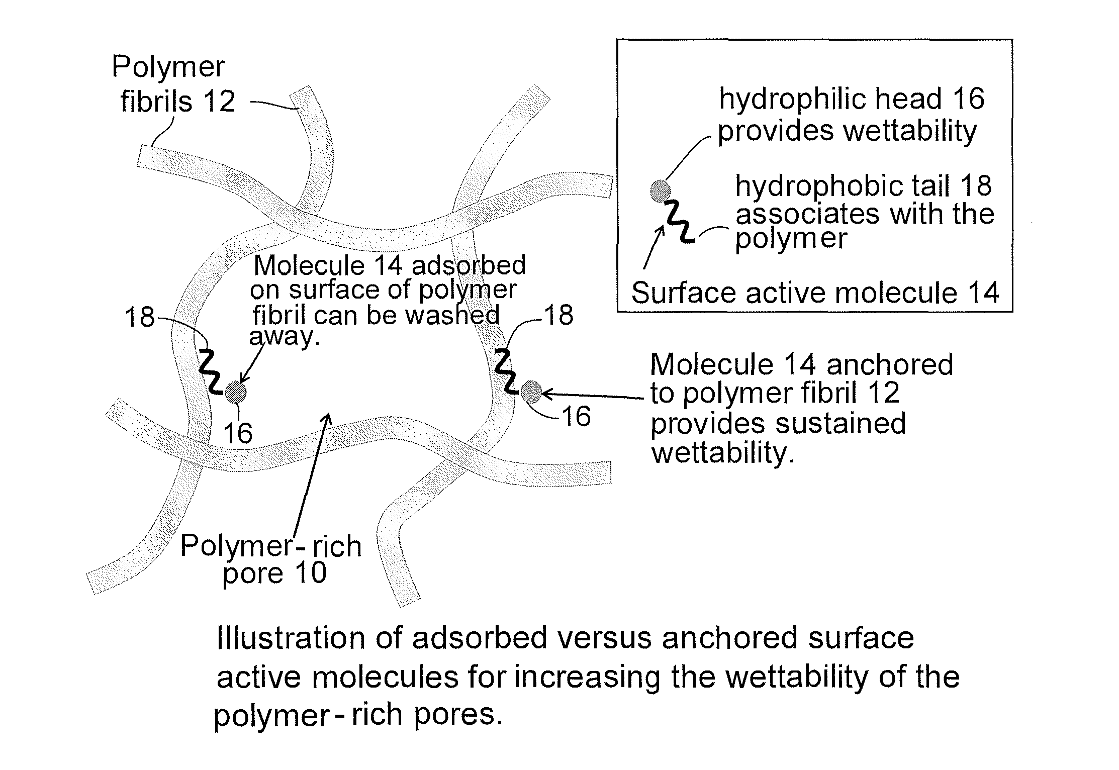
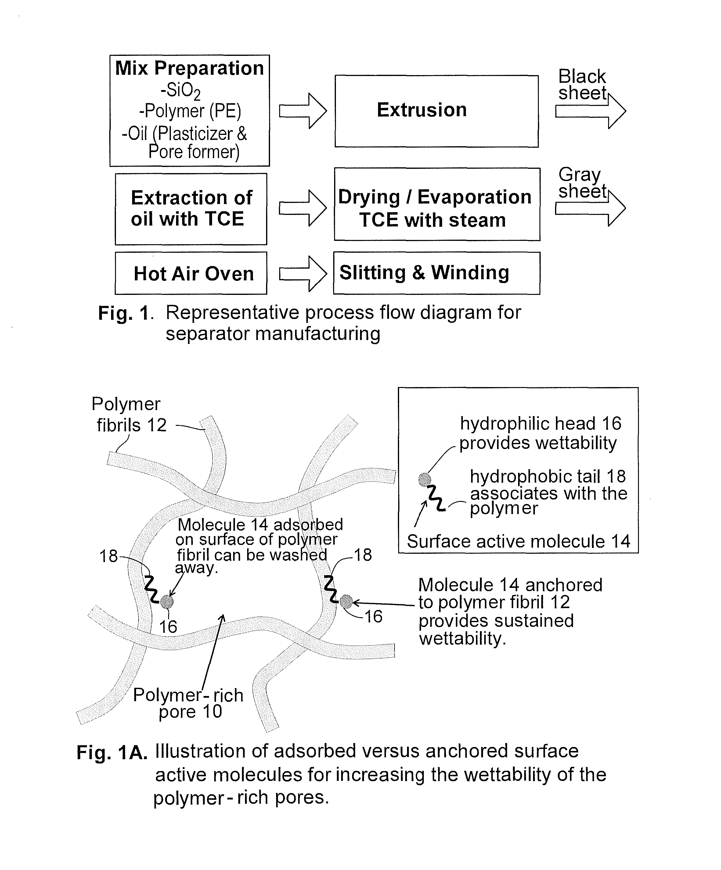
It is believed that surfactants with long alkyl side chains, such as sodium dodecylbenzene sulfonate, can interact with UHMWPE during the extrusion process such that it becomes “anchored” to the polymer matrix and cannot be easily washed away.

Method used


Image

  • Lead-acid battery separators with ultra low resistivity and sustained wettability
  • Lead-acid battery separators with ultra low resistivity and sustained wettability
  • Lead-acid battery separators with ultra low resistivity and sustained wettability

Examples


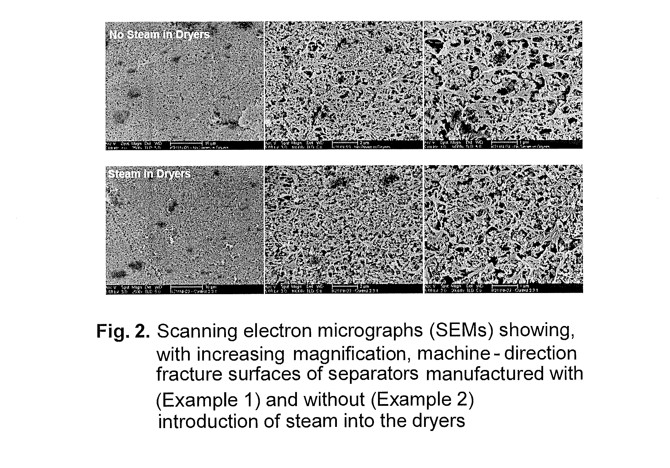
example 1

[0033]The following materials were place in a batch mixer and blended together:

[0034]44 kg UHMWPE (U090; KPIC)

[0035]120 kg Precipitated silica (1165 MP milled; Rhodia)

[0036]75 kg Recycled pellets (65% oil+25% silica+10% UHMWPE)

[0037]3.23 kg Colorant (50% C black+50% HDPE)

[0038]0.58 kg Antioxidant (hindered phenol)

[0039]0.58 kg Lubricant (Ca / Zn stearate).

[0040]Next, 69.6 gals (263.4 liters) of Nytex 820 oil were sprayed onto the blended materials under agitation to form a mixture having the consistency of damp sand. This mixture was then fed to a counter-rotating twin screw extruder at 660 kg / hr. Additional oil was added in-line at the extruder to bring the final oil content to about 66 wt. %. The melt temperature was approximately 231° C. as the melt passed through the sheet die and entered into the calender stack, where the rib pattern and thickness were controlled. The oil-filled sheet was subsequently extracted with trichloroethylene (TCE) and then dried to form the final separat...

example 2

[0042]Separators were manufactured in accordance with the formulation and process conditions outlined in Example 1, except that TCE was allowed to evaporate from the sheet with no steam delivered to the dryer.

example 3

[0043]Separators were manufactured in accordance with the formulation and process conditions outlined in Example 1, except that the sheet was dip-coated with a 2.5 wt. % aqueous solution of sodium dihexyl sulfosuccinate (Aerosol® MA-80; Cytec Industries) prior to entering the hot air oven. The finished separator rolls had high moisture content (about 30 wt. %) because of the limited path length and short residence time they underwent in the hot air oven (see FIG. 1). Separator samples were further dried in a convection oven at 105° C. prior to testing.


PUM

PropertyMeasurementUnit
Size distributionaaaaaaaaaa
Pore sizeaaaaaaaaaa
Pore size distributionaaaaaaaaaa

Abstract

A lead-acid battery separator with ultralow resistivity results from high porosity, controlled pore (10) size distribution, and an ionic surfactant (14) with a long alkyl side chain (18) that is anchored to the polymer matrix (12) of a silica-filled polyethylene separator. The surfactant cannot be easily removed or washed away and thereby imparts sustained wettability to the separator. Controlling the number of, and volume occupied by, the pores (i.e., porosity) and pore size distribution of the separator contributes to a reduction in electrical (ionic) resistivity.

Description

RELATED APPLICATIONS[0001]This application claims benefit of U.S. Patent Application Nos. 61 / 868,478 and 61 / 792,631, filed Aug. 21 and Mar. 15, 2013, respectively.TECHNICAL FIELD[0002]This invention relates to manufacture of separators for use in lead-acid batteries and, in particular, to the practice of specific process technologies and interface modifications for the manufacture of microporous separators installed in lead-acid batteries configured for use in extended cycling applications.BACKGROUND INFORMATION[0003]The lead-acid storage battery is commonly found in two modes of design: the valve-regulated recombinant cell and the flooded cell. Both modes include positive and negative electrodes typically in the form of plates that are separated from each other by a porous battery separator. The porous separator prevents the electrodes from coming into physical contact and provides space for an electrolyte to reside. Such separators are formed of materials that are chemically resis...

Claims


Application Information

Patent Timeline
IPC IPC(8): B29C47/00B29C71/00H01M50/403H01M50/406H01M50/417H01M50/434H01M50/491
CPCH01M2/166B29L2031/3468B29C47/0021B29C71/0009H01M10/06H01M2220/20B29C2071/0027B29K2023/0683B29K2105/16B29K2509/00B29K2995/0081B29K2995/0003B29K2995/0068B29L2007/008H01M2/145B29C48/08Y02E60/10H01M50/403H01M50/44H01M50/417H01M50/406H01M50/491H01M50/434Y02P70/50H01M50/446
Inventor PEKALA, RICHARD W.LA, CHI THUONG-LEROGERS, CORY S.FRENZEL, JEFFRY M.WATERHOUSE, ROBERTWALKER, DAVID P.
Owner AMTEK RES INT
Learn More