Powder coating (electrostatic painting) method and plant for non electrically conductive elements, and in particular brake pads

Active Publication Date: 2016-02-11
ITT ITAL SRL
View PDF5 Cites 6 Cited by
  • Summary
  • Abstract
  • Description
  • Claims
  • Application Information

AI Technical Summary

Benefits of technology

[0020]In particular these results are obtained by means of two constructive features: on one hand the nozzles are aligned in line to one another underneath the motorized roller rack, so that their jets are aimed from below upwards at a predetermined vertical distance from the motorized roller rack, leaving an empty space, possibly adjustable, between the rack and the nozzles; and on the other hand the extraction hood is defined by a tubular element provided with a straight collection slit facing the nozzles in the same direction of alignment as the nozzles themselves. As a matter of fact, it has been found that when these two constructive features are present at the same time, they ha

Problems solved by technology

NAO compounds, due to their composition, have an electric conductivity not sufficient to ensure a good painting thereof; things are even worse if the copper is eliminated (due to environment care compounds without copper are more and more requested).
Even though in brake pads the compound is manufactured as a plaque or pad assembled on a metal plate in order to form the actual brake pad, painting brake pads made with non electrically conductive materials presents numerous problems.
In particular, it is presently impossible to utilize currently used powder coating plants built to coat/paint brake pads that are electrically conductive.
However, conductive primers are based on organic solven

Method used


Image

  • Powder coating (electrostatic painting) method and plant for non electrically conductive elements, and in particular brake pads
  • Powder coating (electrostatic painting) method and plant for non electrically conductive elements, and in particular brake pads
  • Powder coating (electrostatic painting) method and plant for non electrically conductive elements, and in particular brake pads

Examples


Embodiment Construction

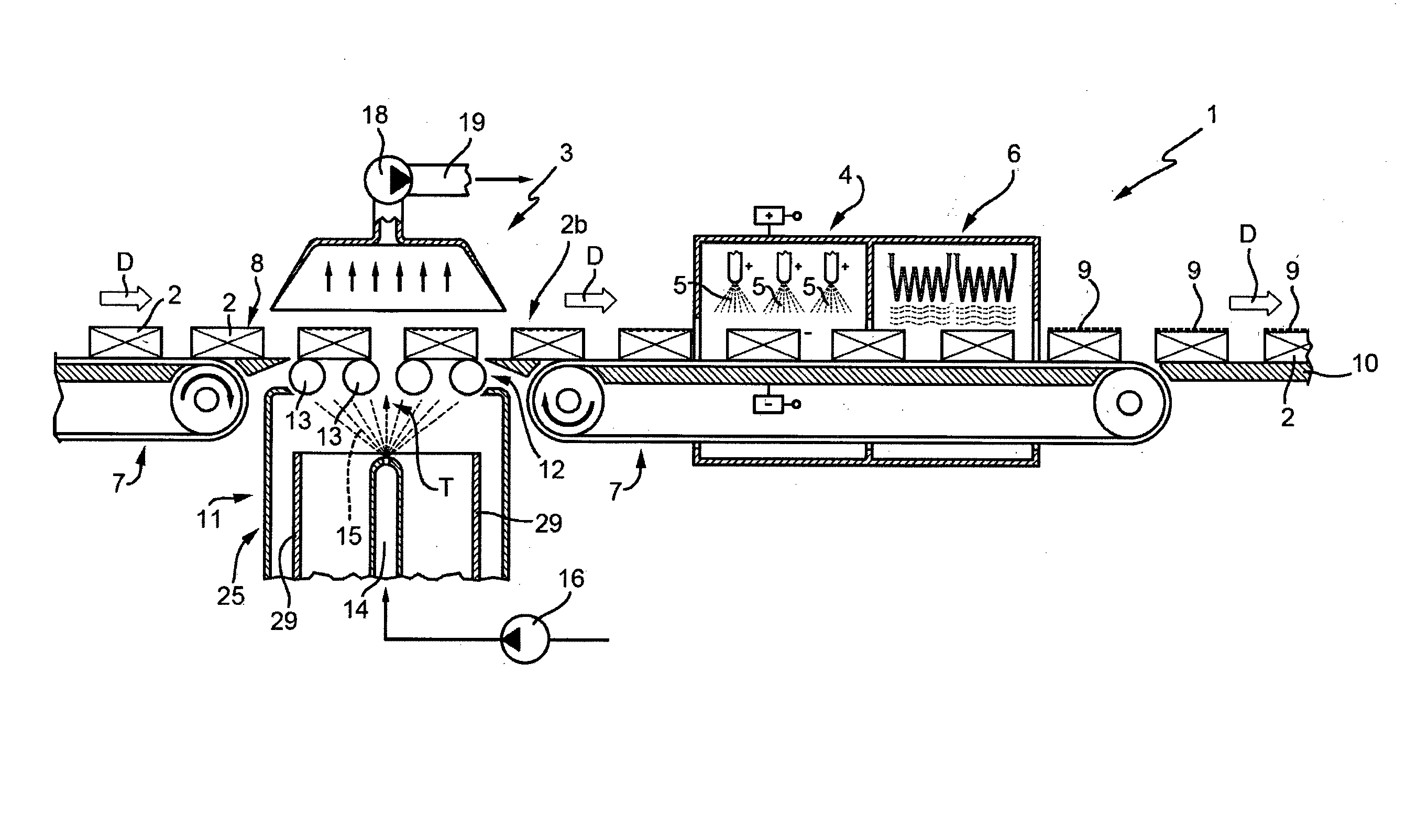
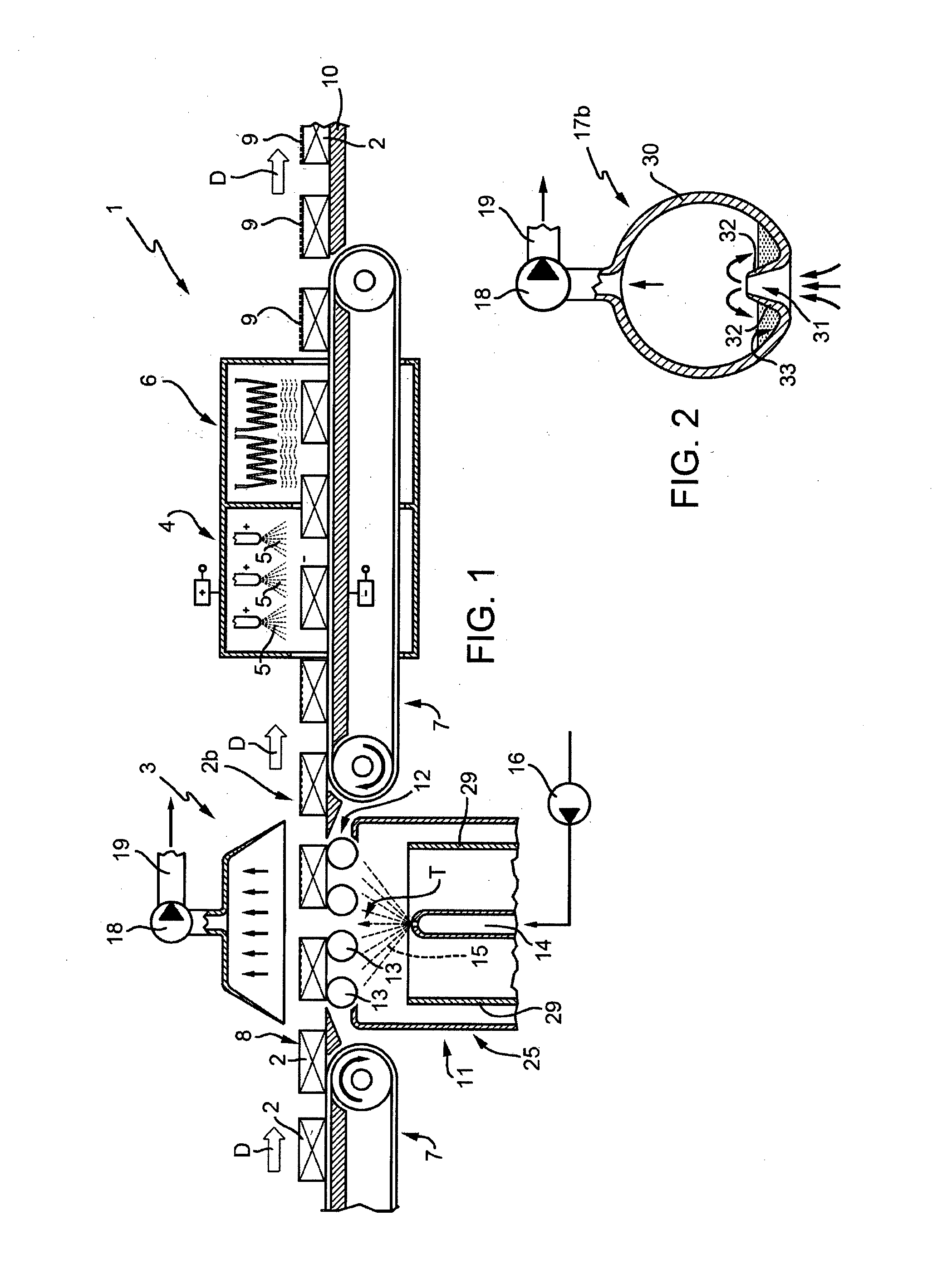
[0029]With reference to FIG. 1, is depicted a powder coating plant, overall indicated with reference number 1, for painting non electrically conductive elements 2, in particular brake pads manufactured with asbestos-free organic friction compounds, known in the art and therefore not shown in detail but only illustrated as blocks.

[0030]Said type of brake pads are initially manufactured by molding the compound at a temperature of between 130 and 200° C. in order to create a plaque or pad, which are subsequently cured by thermal treatment, assembled onto an iron metal support, and finally painted together with the support.

[0031]NAO brake pad compounds obtained in this manner however, using previously existing technologies, cannot be powder coated but only spray painted, with all the associated issues, including protection of the environment, that this implies.

[0032]According to the invention, on the contrary, the powder coating plant 1 is utilized, which in general comprises a pre-trea...


PUM

PropertyMeasurementUnit
Temperatureaaaaaaaaaa
Pressureaaaaaaaaaa

Abstract

A method and system for powder coating non electrically conductive elements, preferably brake pads. A pre-treatment station is upstream of an electrostatic powder coating deposition station and a baking station for melting and polymerizing the powder coating in order to form a coating layer on a surface to be coated. The pre-treatment station causes the elements to be coated to conduct electrically by uniformly wetting said elements by means of creating poorly mineralized water covalent bonds on at least one surface to be coated, in an amount aimed at producing a measurable weight increase in the non electrically conductive elements, which then causes them to conduct electrically. The water adsorbed and/or deposited is subsequently eliminated within the baking station.

Description

CROSS-REFERENCE TO RELATED APPLICATIONS[0001]This application is a national stage application under 35 U.S.C. §371 of International Application No. PCT / IB2013 / 060115, filed Nov. 13, 2013, which claims priority of Italian Patent Application No. TO2012A000981, filed Nov. 13, 2012, the entire contents of each application being herein incorporated by reference.TECHNICAL FIELD[0002]The present invention relates to a method and process for powder coating non electrically conductive elements, and in particular brake pads made with NAO (“Non Asbestos Organic” i.e. asbestos-free organic friction) friction materials.TECHNICAL BACKGROUND[0003]Friction materials utilized as the lining in drum brake shoes of drum brakes and in the brake pads in automobile disk brakes and other devices (for example in clutch plates) are manufactured with a compound (mixture) comprising a fibrous or fiber material, an organic binder (usually a phenolic synthetic resin) and a bulk or “filler”. Instead of asbestos a...

Claims


Application Information

Patent Timeline
IPC IPC(8): B05D1/04B05B5/00B05B5/08B05D1/06B05D3/02
CPCB05D1/045B05D1/06B05B5/082B05B5/001B05D3/0272F16D69/00F16D2250/0046B05B5/1608B05B13/0447B05B13/0457B05C9/10B05C19/002B05D3/005B27K3/15B05B14/30B05B16/20B05B16/60B05B16/95
Inventor TARASCO, PIER LUIGI
Owner ITT ITAL SRL
Why Eureka
Try Eureka