System for processing water and generating water vapor for other processing uses

a technology for processing water and other processing uses, applied in water conservation, machine/engine, combination process, etc., can solve the problems of large-scale desalinization, high cost, high infrastructure, etc., and achieve the effect of reducing fluid pressure, increasing fluid velocity, and reducing fluid pressur

Active Publication Date: 2016-02-18
VERNO HLDG
View PDF7 Cites 8 Cited by
  • Summary
  • Abstract
  • Description
  • Claims
  • Application Information

AI Technical Summary

Benefits of technology

[0025]The means for centrifugally and axially compressing vaporizes at least part of the fluid through cavitation such that the fluid comprises non-vaporized dissolved solids, a liquid and a vapor. The means for centrifugally and axially compressing causes centrifugal compression of the fluid, resulting in the non-vaporized dissolved solids and at least part of the liquid moving toward an outer wall of the vessel. The means for centrifugally and axially compressing causes axial flow compression of the liquid and vapor increasing the pressure of the fluid.
[0034]The system preferably includes a filtration device between the pump motor and the fluid inlet to remove solid matter from water being delivered by the pump. A filter screen over the open sides, preferably behind the louvers of the capture vessel, prevents large objects from entering the capture vessel and potentially clogging the funnel or other component of the system. The body of water preferably is a source of salt water, such as a sea or ocean, such that the fluid processed by the system is salt water and the processing comprises desalination of the salt water.

Problems solved by technology

But, desalinization is increasingly being used in arid regions having scarce fresh water resources.
Large-scale desalinization is typically costly and generally requires large amounts of energy and an expensive infrastructure.
But, these systems still require significant energy input to evaporate the water.
The membranes themselves are stored in expensive and highly pressurized containers.
Alternatively, centrifuges are typically more efficient, but are more difficult to implement.
One common problem with reverse osmosis in general is the removal of suspended salt and clogging of the membrane over time.
While reverse osmosis works well with somewhat brackish water solutions, reverse osmosis may become overloaded and inefficient when used with heavily salted solutions, such as ocean salt water.
Other, less efficient desalinization methods may include ionic exchange, freezing, geothermal desalinization, solar humidification (HDH or MEH), methane hydrate crystallization, high-grade water recycling or RF induced hyperthermia.
Regardless of the process, desalinization remains energy intensive.
Future costs and economic feasibility continue to depend on both the price of desalinization technology and the costs of the energy needed to operate the system.
In fact, net energy use is essentially equivalent to pump loss and heat loss from equipment operation.
One drawback of this design is that the rotating shaft is built into a vertical chamber.
At high rotational speeds (e.g. over Mach 1), vibrations cause excessive bearing shaft and seal failure.
Another drawback is that a series of chambers are bolted together in housing sections.
The housing and O-ring seals tend to wear over time due to salt penetration because the multiple chambers and housing sections are connected via a plurality of nuts and bolts.
In particular, the assembly of the Wallace design is particularly laborious.
Maintenance is equally labor intensive as it takes significant time to disassemble each of the housing sections, including the O-rings, nuts and bolts.
The system is also prone to a variety of torque and maintenance problems as the device ages, such as O-ring leakage.
Moreover, the rotating shaft is connected to the power source by a gear drive, which contributes to the aforementioned reliability problems associated with the bearings, shafts and seals.
The system also fails to disclose a means for regulating the speed of the rotating shaft sections according to the osmotic pressure of the salt water being desalinated.
The static operation of the Wallace desalinization machine is therefore not as efficient as other modern desalinization devices.

Method used


Image

  • System for processing water and generating water vapor for other processing uses
  • System for processing water and generating water vapor for other processing uses
  • System for processing water and generating water vapor for other processing uses

Examples


Embodiment Construction

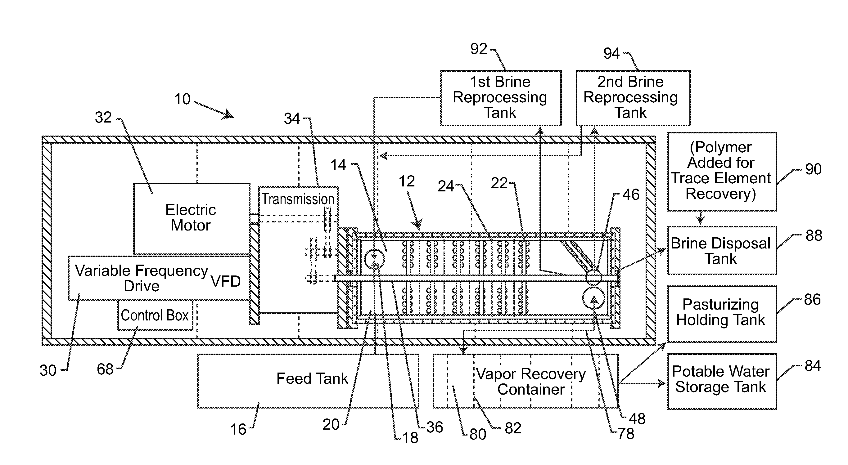
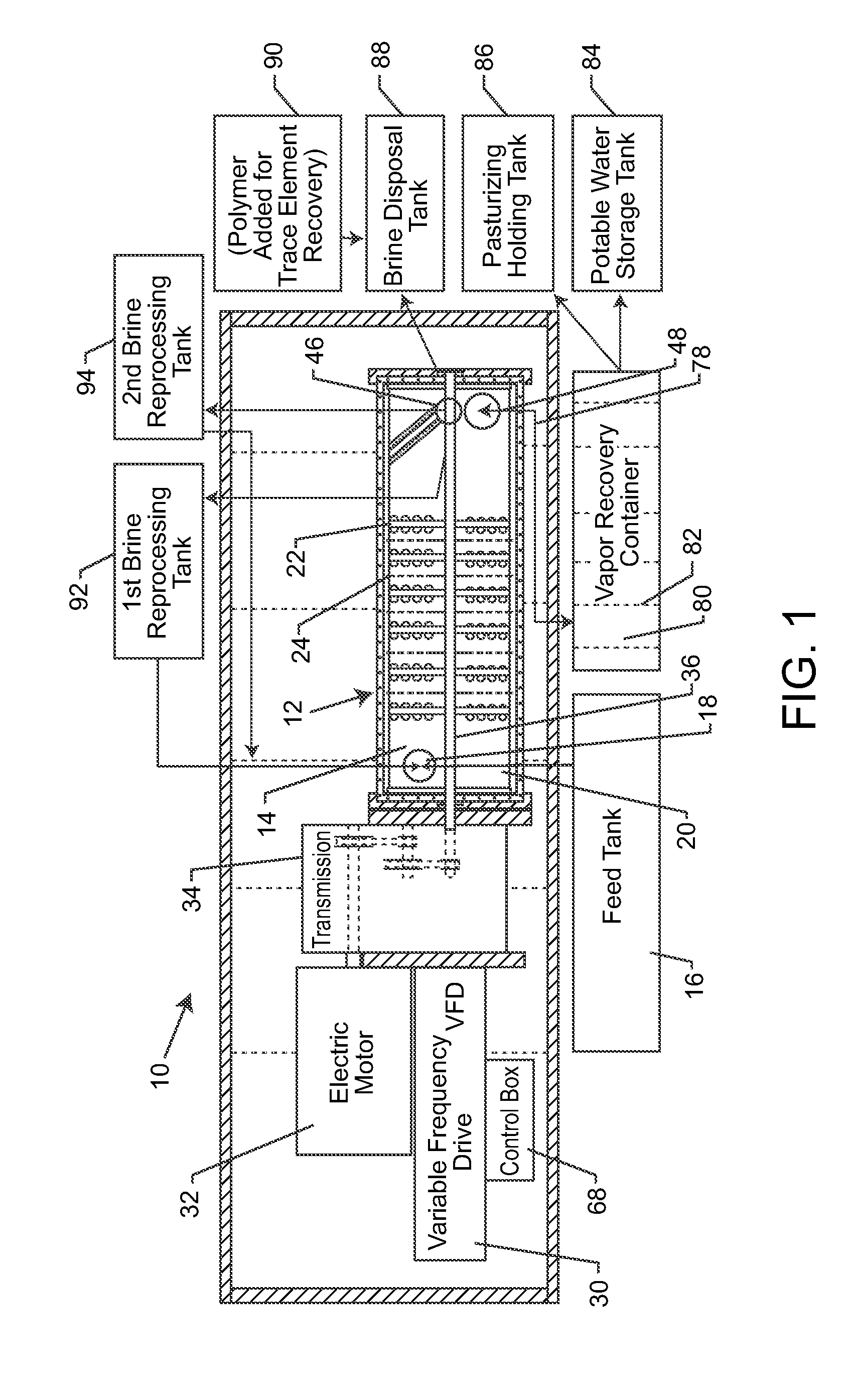
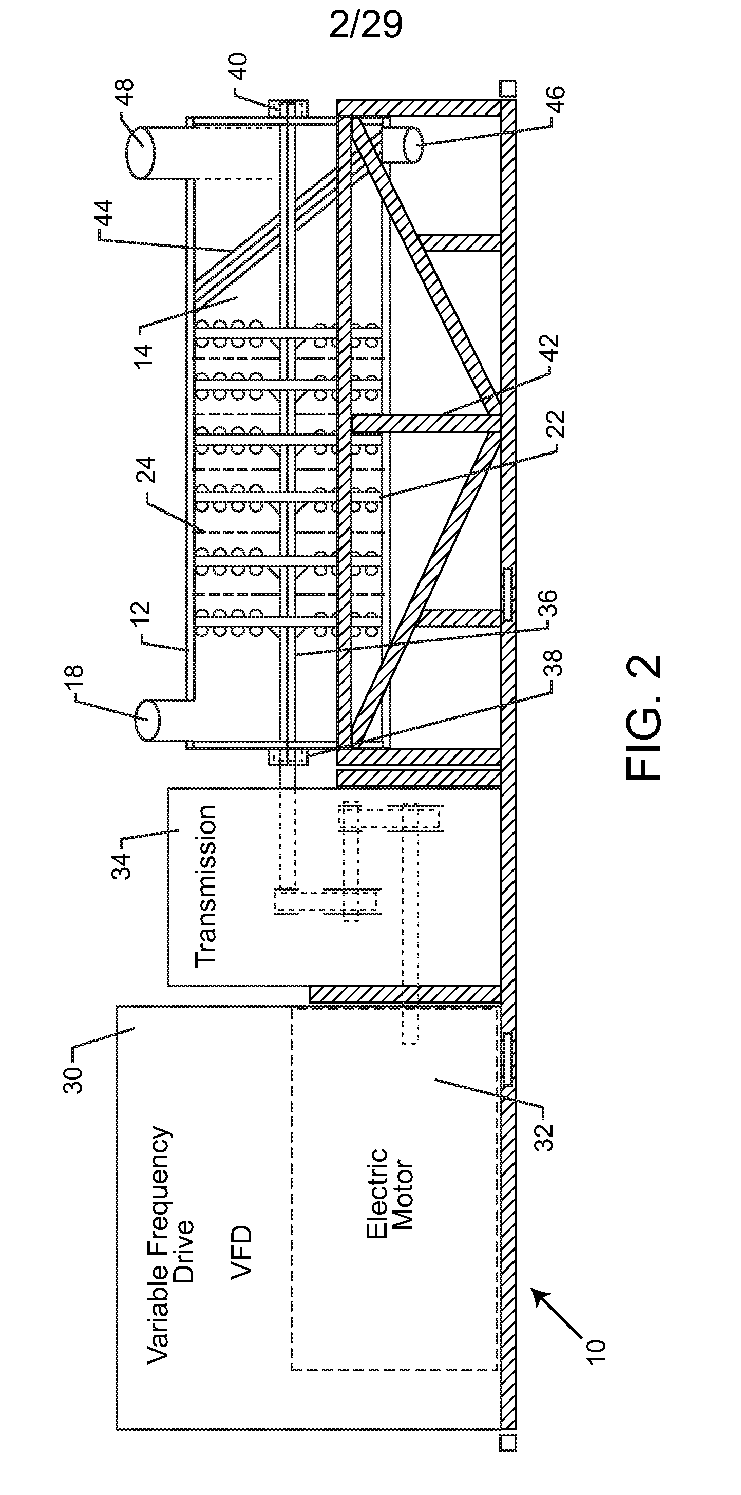
[0088]As shown in the drawings, for purposes of illustration, the present invention resides in a system and method for decontaminating water and generating water vapor. The method and system of the present invention is particularly suitable for desalinization of salt water, such as ocean or other brackish waters, as well as, river water or other liquids / slurries. This preferred treatment will be used for exemplary purposes herein, although it will be understood by those skilled in the art that the system and method of the present invention could be used to decontaminate other water sources. The present invention may be used to remove dissolved or suspended solids (decontamination), as well as, heavy metals and other pollutants. Moreover, as will be more fully described herein, the system and method of the present invention can be used in association with relatively clean water to create water vapor, in the form of steam, which has a sufficient pressure and temperature so as to be pa...


PUM

PropertyMeasurementUnit
distanceaaaaaaaaaa
distanceaaaaaaaaaa
angleaaaaaaaaaa

Abstract

A system for processing a fluid by generating water vapor through forced compression and rotation in a vessel includes capturing sea water for use in desalination processing in the vessel. Any fluid processed in the vessel, including sea water, can be used to create water vapor that rises to an elevation under its own power. After condensing the water vapor to liquid again, the condensed liquid falls upon a hydro-electric generator to generate electricity that is stored for later use. Brine output from the system can be recycled for re-processing through the system to increase water vapor yield. The wet brine output may also be dried to produce dried brine for subsequent processing of salt and other minerals.

Description

RELATED APPLICATIONS[0001]This application is a continuation-in-part of U.S. application Ser. No. 14 / 096,334, filed Dec. 4, 2013, which was a divisional of U.S. application Ser. No. 13 / 536,581, filed Jun. 28, 2012 (now U.S. Pat. No. 9,102,545), and was a continuation-in-part of U.S. application Ser. No. 12 / 488,750, filed Jun. 22, 2009 (now U.S. Pat. No. 8,562,791).BACKGROUND OF THE INVENTION[0002]The present invention relates to a system for decontaminating water and generating water vapor. More particularly, the present invention relates to an improved method that utilizes a series of sensors and a control system to vaporize water, remove dissolved solids and maximize recovery of potable water from contaminated water via a horizontal water processing vessel.[0003]Desalinization (also desalination or desalinisation) refers to one of many processes for removing excess salt, minerals and other natural or unnatural contaminants from water. Historically, desalinization converted sea wat...

Claims


Application Information

Patent Timeline
Patent Type & Authority Applications(United States)
IPC IPC(8): C02F1/04B01D1/00B01D1/22B01D1/24B01D3/08C02F1/08F03B13/00
CPCC02F1/048B01D1/223B01D1/228B01D1/24B01D1/0082C02F2303/10C02F1/08F03B13/00C02F2103/08C02F2209/005B01D3/08B01D1/225C02F1/18C02F2209/02C02F2209/40C02F2209/42F22B3/06Y02A20/00Y02A20/124Y02W10/37
Inventor RILEY, JOHN D.JOHNSON, DANA L.
Owner VERNO HLDG
Why Eureka
Try Eureka