All-organic inductor-capacitor tank circuit for radio frequency sensor applications

a technology of inductance and capacitor, applied in the field of inductance capacitor, can solve the problems of high resistivity, failure to make such sensors, etc., and achieve the effects of poor conductivity, less usability, and affecting the resistance, inductance and capacitance of the circui

Active Publication Date: 2016-02-18
BREWER SCI
View PDF5 Cites 17 Cited by
  • Summary
  • Abstract
  • Description
  • Claims
  • Application Information

AI Technical Summary

Benefits of technology

[0030]In addition to the above shortcomings, growing CNTs on flexible (mostly polymeric) substrates significantly alters the substrate in a way that is destructive for device fabrication. Further, the CNTs are likely to (mostly) align vertically when grown—from the substrate surface to the top of the film. This can result in poor conductivity in the direction of the inductor coil, making it less usable. The present invention results in random direction CNTs, which is better than the vertical alignment of as-grown CNTs.
[0031]It will be appreciated that the inventive tank circuit can comprise both the above-described inductor and capacitor, or one or the other paired with a commercially available version of the other. In other words, the circuit can comprise the above inductor with a commercially available capacitor, or the above conductor with a commercially available inductor. Ideally, the tank circuit is essentially entirely organic (i.e., less than about 2% by weight, preferably less than about 1% by weight, and preferably about 0% by weight of inorganic material such as silicon, metal oxides, and ceramics, based upon the total weight of the circuit components taken as 100% by weight). This is achieved by using essentially entirely organic capacitors and inductors having these same low percentages of inorganic material.
[0032]The inductor and capacitor could be wired into the circuit via conventional connection methods, although it is particularly preferred that it be wired with fully combustible (i.e., essentially all organic) materials (e.g., CNT traces). The physical layouts of the inductor and capacitor circuit could vary. For instance, they can be put down on one side of a substrate or two sides of a substrate. Alternatively, the individual components can be put down side-by-side in the substrate plane. The individual components can be put down layer by layer in the substrate plane. They could be in series or parallel, but will most preferably be in parallel. The individual components can be stand-alone inductors or capacitors, or parasitic inductors or capacitors. Furthermore, although the present invention is described in the context of a passive circuit, it will be appreciated that active devices can also be included in the circuit, with exemplary active devices being selected from the group consisting of vacuum tubes, transistors, ring oscillator, inverter, amplifier, diodes, memory, micro-controller, display, analog devices, and logic devices.
[0033]The inventive circuit is preferably in communication with a sensor (e.g., radio simulation source). The sensor can be selected depending upon the particular condition to be detected. The proposed sensor uses the resonant frequency induced by the electromagnetic energy (VHF and UHF) from the (preferably) passive “tank” resonance circuit to measure the temperature, humidity, or other environmental changes. The radio-excited system works by using electromagnetic VHF and UHF radiation pulses incident on a classical “tank” resonant circuit that oscillates at a single frequency, fr.
[0034]The resonant frequency of the tank circuit and the amplitude of the resonant signals can be modulated by a thermal, mechanical, or chemical signal. Specifically, changes in the signal would affect the resistance, inductance, and capacitance of the circuit. Once that change is detected, a transmitter can transmit a signal to a receiver to alert as to the existence of the changed condition. Suitable sensors (and their accompanying conditions) include those selected from the group consisting of temperature sensors, strain sensors, vibration sensors, humidity sensors, stress sensors, moisture sensors, blast sensors, and structural sensors. As a specific example, for one embodiment, a battery-powered source can be made so that during a temperature query, the source emits a pulse train that stimulates the tank circuit. The tank circuit oscillations can then be detected by the receiver. The resonant frequency of the tank transmissions can be measured and the temperature calculated.
[0035]Any carbon nanotube solution (or dispersion) that is capable of forming films and electrodes having the above properties is suitable for use in the present invention. Suitable CNTs for use in the present inventive method include any raw single-walled, double-walled, or multi-walled CNTs (SWCNTs, DWCNTs, and MWCNTs, respectively). Preferably, the CNTs are pristine, that is, CNTs having little or no sidewall defects, existing functionalization, or doping. Non-pristine CNTs may be used, but the existing functionalization or doping may be damaged by the acid treatment, and the resulting conductivity might be affected. Exemplary types of CNTs for this process include, but are not limited to, CG200 CNTs and SG65 CNTs (available from SWeNT), XBC3350 CNTs (available from CCNI), HiPco™ CNTs (available from NanoIntegris), as well as those available from Thomas Swan and CheapTubes.

Problems solved by technology

There have been attempts to make such sensors without success.
One of the issues for CNT inductor coils is their high resistivity.

Method used


Image

  • All-organic inductor-capacitor tank circuit for radio frequency sensor applications
  • All-organic inductor-capacitor tank circuit for radio frequency sensor applications
  • All-organic inductor-capacitor tank circuit for radio frequency sensor applications

Examples


example 1

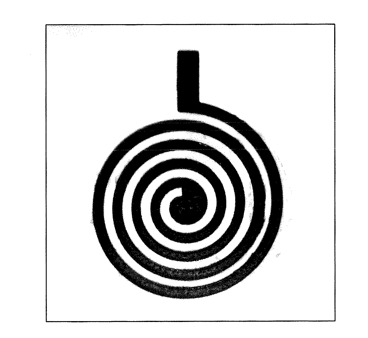
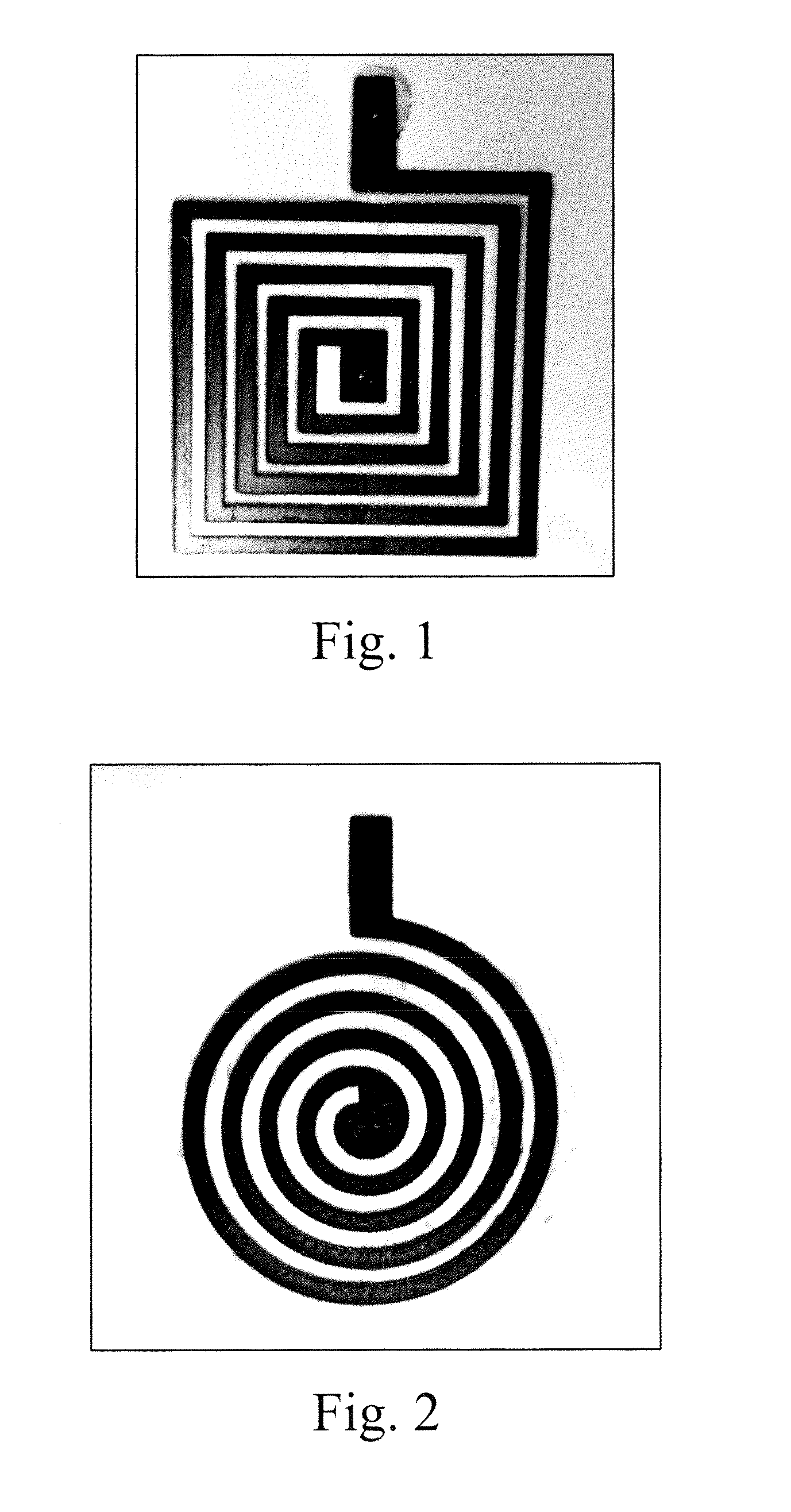
Printing of Circular and Rectangular CNT Inductor Coils

[0047]The inductor coils were deposited on a polyethylene terephthalate (“PET”) substrate by spray coating a solution of CNTs functionalized with 1-pyrenemethylamine (CNTRENE® 3010 A8-R, Brewer Science, Inc., Rolla, Mo.). The spray coater was equipped with a Sonotek ultrasonic spray nozzle. The spray nozzle was located at about 1.5 inch above the substrate surface (sitting on a heated platen) with the sonication power set at 3 W. The material spray rate was set at 10 mL / hour. The spray coating line space was set at 1 mm with a spray coating speed of 60 mm / sec. A 0.007 inch thick tungsten stencil with the desired inductor coil pattern was placed on top of the substrate surface. Spray coating was carried out using the above-mentioned parameters. Multiple layer of coatings was required to achieved the desired thickness / resistance.

[0048]After deposition, the platen was heated to 130° C., and no post-deposition processing was necessa...

example 2

Testing of CNT Inductor Coil with Commercially Available Capacitor

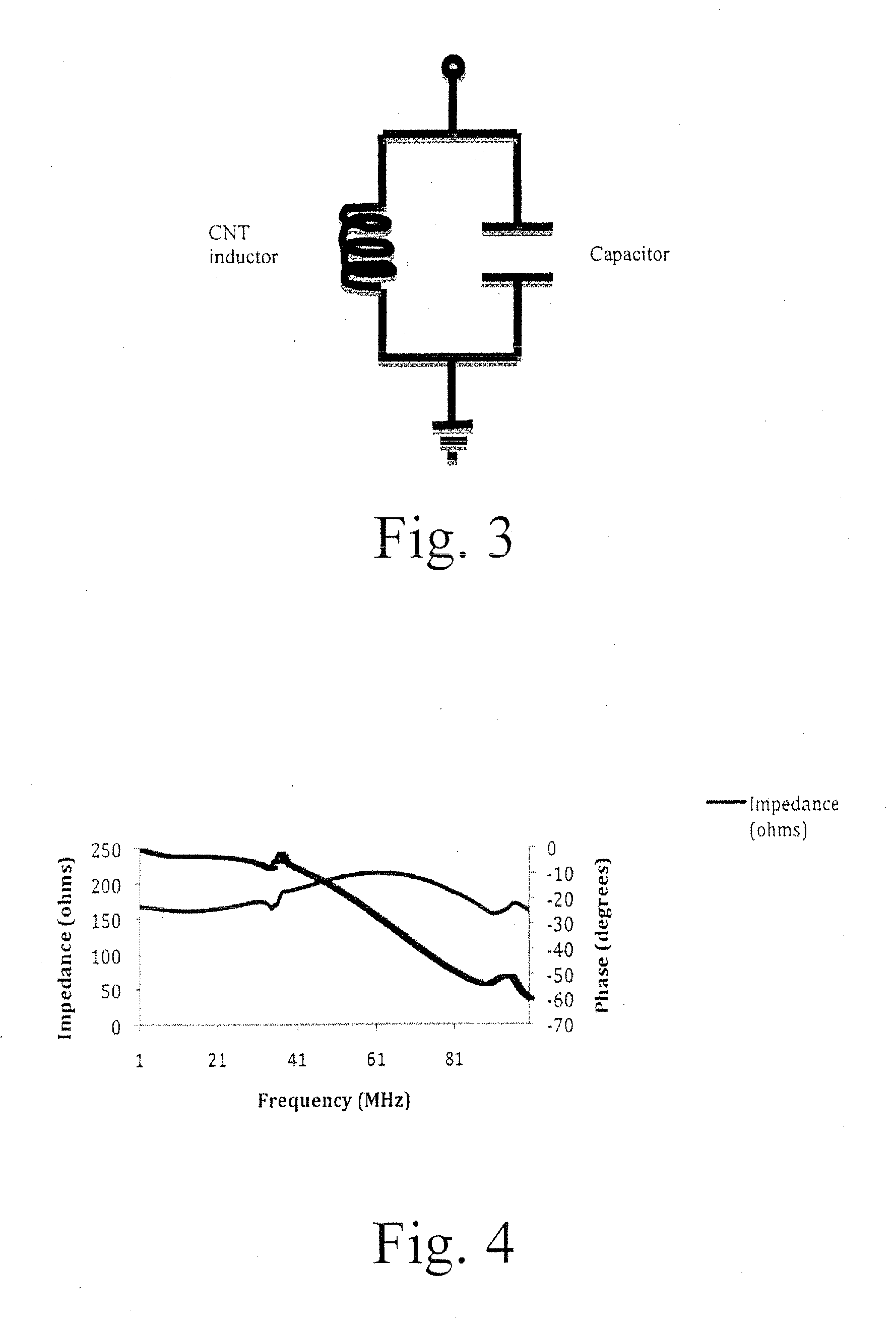
[0049]The circular CNT-based inductor coil from Example 1 was wired to a prototype circuit board as shown in FIG. 3. The capacitor used was a 12 pF Ceramic capacitor (XICON Passive Components, Arlington, Tex.). The circuit board was connected to the impedance test kit and an impedance analyzer (HP4195A, Agilent Technologies, Santa Clara, Calif.) by RF connectors. The input into the circuit was 500 mV.

[0050]An impedance and phase plot of the CNT inductor was created using an impedance analyzer. FIG. 4 shows this plot for the CNT inductor with the 12 pF capacitor.

example 3

Testing of CNT Capacitor with a Commercially Available Inductor

[0051]A CNT capacitor was made by spray coating the CNT solution used in Example 1 to form electrodes. A commercial grade polyimide thin film (Kapton, from DuPont) was used as the dielectrics. The wiring scheme was the same as that shown in FIG. 3. FIG. 5 shows the impedance and phase plot for a 1-μH polystyrene film inductor (XICON Passive Components) with the CNT capacitor. The input into the circuit was 500 mV.


PUM

PropertyMeasurementUnit
thicknessaaaaaaaaaa
thicknessaaaaaaaaaa
thicknessaaaaaaaaaa

Abstract

The present invention provides novel tank circuits that are totally passive, and they are made of conductive-grade carbon nanotubes (CNTs) on substrates, and preferably flexible substrates. These components and structures contain no traditional electronic materials such as silicon, metal oxides, or ceramics, and they are totally organic. They may be used in applications where the resonant frequency and amplitude of the sensor can be modulated by a thermal, mechanical, or chemical signal, such as temperature, strain, pressure, vibration, or humidity. All-organic, and consequently combustible, passive RF sensors have unique applications for defense and consumer industries.

Description

RELATED APPLICATIONS[0001]This application claims the priority benefit of a provisional application entitled ALL-ORGANIC INDUCTOR-CAPACITOR TANK CIRCUIT FOR RADIO FREQUENCY SENSOR APPLICATIONS, Ser. No. 61 / 635,119, filed Apr. 18, 2012, incorporated by reference herein.FEDERALLY SPONSORED RESEARCH OR DEVELOPMENT[0002]This invention was made with government support under contract number WK15QKN-11-9-001-RP1-B awarded by the Department of Defense. The United States Government has certain rights in the invention.BACKGROUND OF THE INVENTION[0003]1. Field of the Invention[0004]The present invention is concerned with tank circuits that contain inductors having coils made from carbon nanotube films and / or capacitors having conductive layers formed from carbon nanotube films.[0005]2. Description of the Prior Art[0006]Passive radio frequency (RF) sensors are useful because they allow information gathering without in situ attachment of powering systems. These sensors can be used for status, si...

Claims


Application Information

Patent Timeline
Patent Type & Authority Applications(United States)
IPC IPC(8): H05K1/16H01F27/28H01G4/008H01G4/14H05K1/03
CPCH05K1/162H01G4/008H01G4/14H05K1/0313H05K1/165H05K2201/0323H05K2201/10151H05K2201/10166H05K2201/10174H05K2201/10159H05K2201/10128H01F27/2804H01G4/40H05K1/097H05K2201/026H01F5/003
Inventor DIAO, LIYONGSHIH, WU-SHENGLAMB III, JAMES E.LANDORF, CHRISTOPHER
Owner BREWER SCI
Why Eureka
Try Eureka