
Method for detecting and describing a transient driving situation

Active Publication Date: 2016-03-17
ROBERT BOSCH GMBH
View PDF12 Cites 0 Cited by
  • Summary
  • Abstract
  • Description
  • Claims
  • Application Information

AI Technical Summary

Benefits of technology

The present invention provides a method for detecting and describing a transient driving situation of a motor vehicle. This method allows for the identification of an indicator that represents the expected engine filling and changes in emissions behavior. This indicator can be used to adjust target values for controlling exhaust gas recirculation, boost pressure / intake manifold pressure, and injection volume. Additionally, the method can trigger the use of an electrical auxiliary compressor or an e-machine to apply control. Overall, this invention improves the accuracy and efficiency of controlling the boost pressure / intake manifold pressure system, which leads to improved fuel efficiency and more precise emissions control.

Problems solved by technology

A rise in particulates with increasing exhaust gas recirculation is problematic.
The principal reason for higher particulate emissions is that the oxygen also necessary for carbon oxidation is limited.
This creates a conflict of objectives between particulate and nitrogen-oxide emissions, especially in diesel engines.
As a result of existing regulatory stipulations for the exhaust test cycle, the requirements for passenger cars regarding reduction of pollutant emissions in dynamic operation have been undemanding.
In a diesel engine, abrupt load changes and rapid load increases result, because of the inertia of the air system, in a delay in boost pressure buildup.
With an EGR rate control system, the result is a smaller air mass and thus elevated particulate emissions.
In systems or operating states dominated by high-pressure EGR, the resulting additional negative effect on boost pressure buildup potentially limits the maximum possible injection volume, with a consequent delay in reaching the desired target torque.
The methods from the existing art for identifying target values for the control function are not sufficient to react, in the control loops for exhaust gas recirculation, turbocharging, and fuel injection, to the state of affairs described above in transient driving situations.
The problem here is that these variables are not relevant in terms of preventing the generation of pollutant emissions.

Method used


Image

  • Method for detecting and describing a transient driving situation
  • Method for detecting and describing a transient driving situation
  • Method for detecting and describing a transient driving situation

Examples


Embodiment Construction

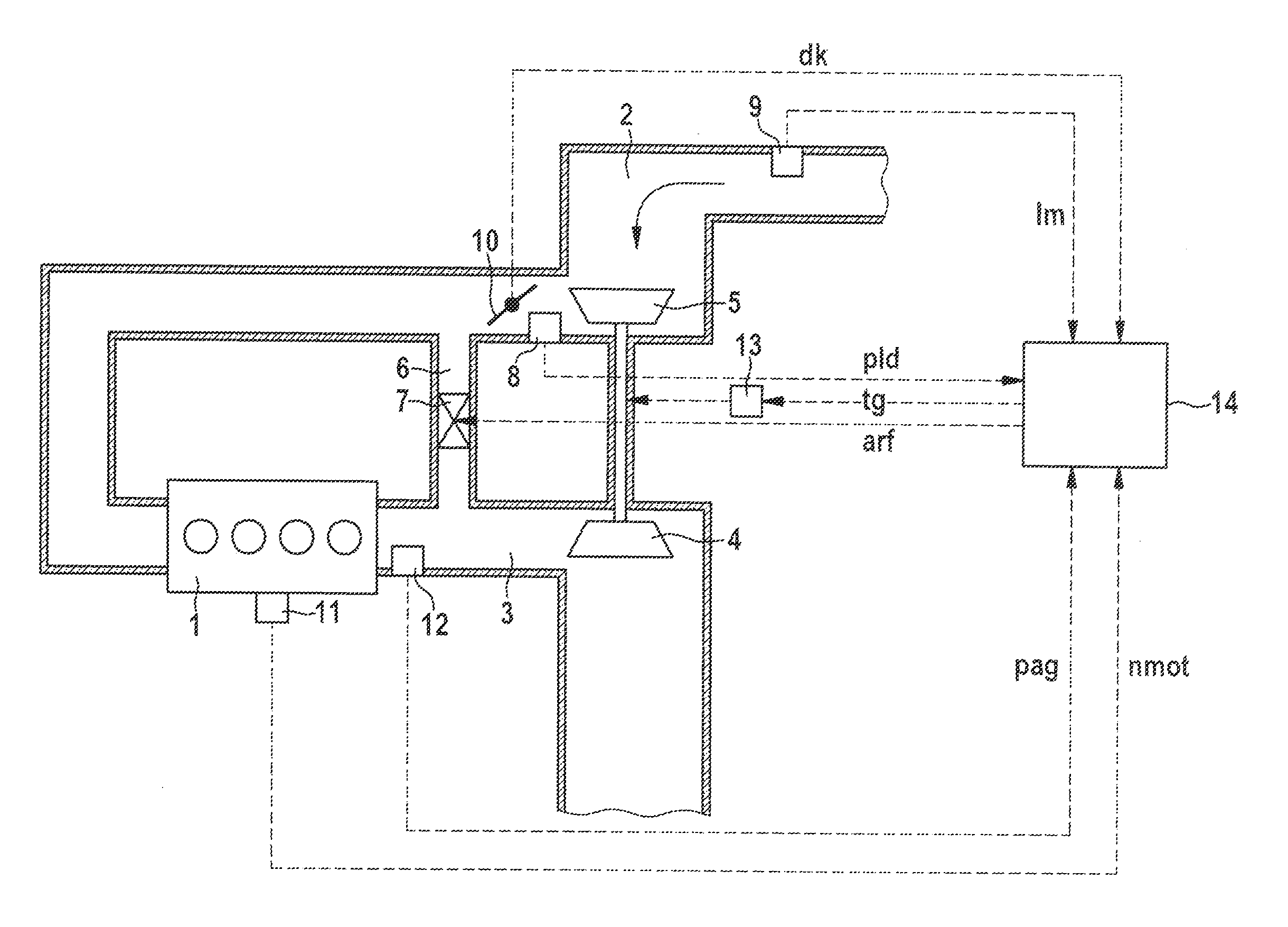
[0028]FIG. 1 depicts an internal combustion engine 1 having an intake duct 2 and an exhaust duct 3. A turbine 4 of an exhaust gas-driven turbocharger is disposed in exhaust duct 3, and a compressor 5 thereof in intake duct 2. The internal combustion engine can be equipped, as depicted, with an exhaust gas recirculation duct 6 that connects exhaust duct 3 to intake manifold 2. An controllable valve 7 is disposed in exhaust gas recirculation duct 6. Control is applied to valve 7 by a control unit 14 that outputs a signal arf. A pressure sensor 8 for measuring the boost pressure is provided in intake manifold 2. The signal pld of boost pressure sensor 8 is delivered to control unit 14. Control unit 14 in turn controls, for example, the turbine geometry of the turbocharger. In order to control the turbine geometry of the turbocharger, control unit 14 outputs a signal tg to an actuating device 13 that adjusts the turbine geometry.

[0029]In addition, a signal dk that characterizes the posi...


PUM


Abstract

A method for detecting and describing a transient driving situation of a motor vehicle having an internal combustion engine having a boost pressure control system or intake manifold pressure control system, wherein an indicator for identifying the transient driving situation is determined from a relative boost pressure / intake manifold pressure control deviation.

Description

RELATED APPLICATION INFORMATION[0001]The present application claims priority to and the benefit of German patent application no. 10 2014 218 221.2, which was filed in Germany on Sep. 11, 2014, the disclosure of which is incorporated herein by reference.FIELD OF THE INVENTION[0002]The present invention relates to a method for detecting and describing a transient driving situation. The present invention further relates to a computer program, a machine-readable data medium for storing the computer program, and an electronic control unit with which the method according to the present invention can be carried out.BACKGROUND INFORMATION[0003]In order to comply with ever more stringent limitations on pollutant emissions, a plurality of actions are taken in present-day engines in order to reduce, in particular, emissions of particulates and of nitrogen oxides.[0004]One essential action is exhaust gas recirculation (EGR), which represents a present-day arrangement for preventing nitrogen oxi...

Claims


Application Information

Patent Timeline
IPC IPC(8): F02D41/26F02B37/24F02D21/08
CPCF02D41/26F02D21/08F02B37/24F02B37/12F02D41/0007F02D41/045F02D41/10F02D41/1401F02D41/2416F02D2041/1432F02D2200/0406F02D2200/0614F02D2200/101F02D2200/70F02M26/05Y02T10/12
Inventor LACHENMAIER, SEBASTIANZELLER, JOHANNESBACHNER, MICHAEL
Owner ROBERT BOSCH GMBH
Learn More