
Microfluidic devices and methods for performing serum separation and blood cross-matching

a microfluidic device and serum separation technology, applied in the field of microfluidic devices and methods for performing serum separation and blood cross-matching, can solve the problems of hematocrit-dependent variation among samples, interfering with cross-match agglutination reactions, colorimetric tests, etc., and requiring sample centrifugation. , the conventional method of serum separation is not amenable to microscale adaptation, and the transfusion of mismatched blood is not easy to

Active Publication Date: 2016-04-21
PERKINELMER HEALTH SCIENCES INC
View PDF4 Cites 14 Cited by
  • Summary
  • Abstract
  • Description
  • Claims
  • Application Information

AI Technical Summary

Benefits of technology

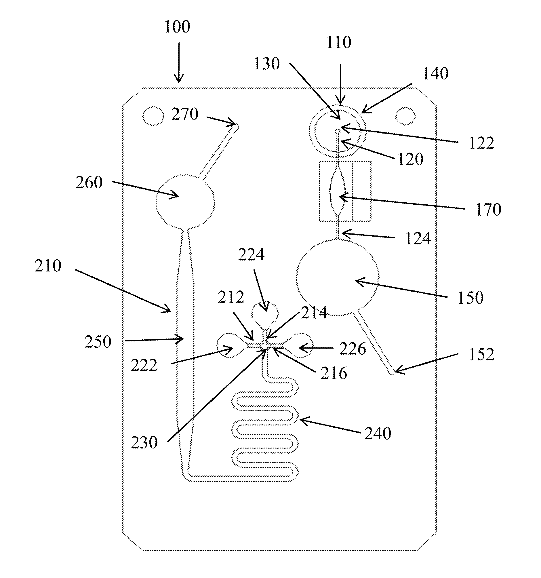
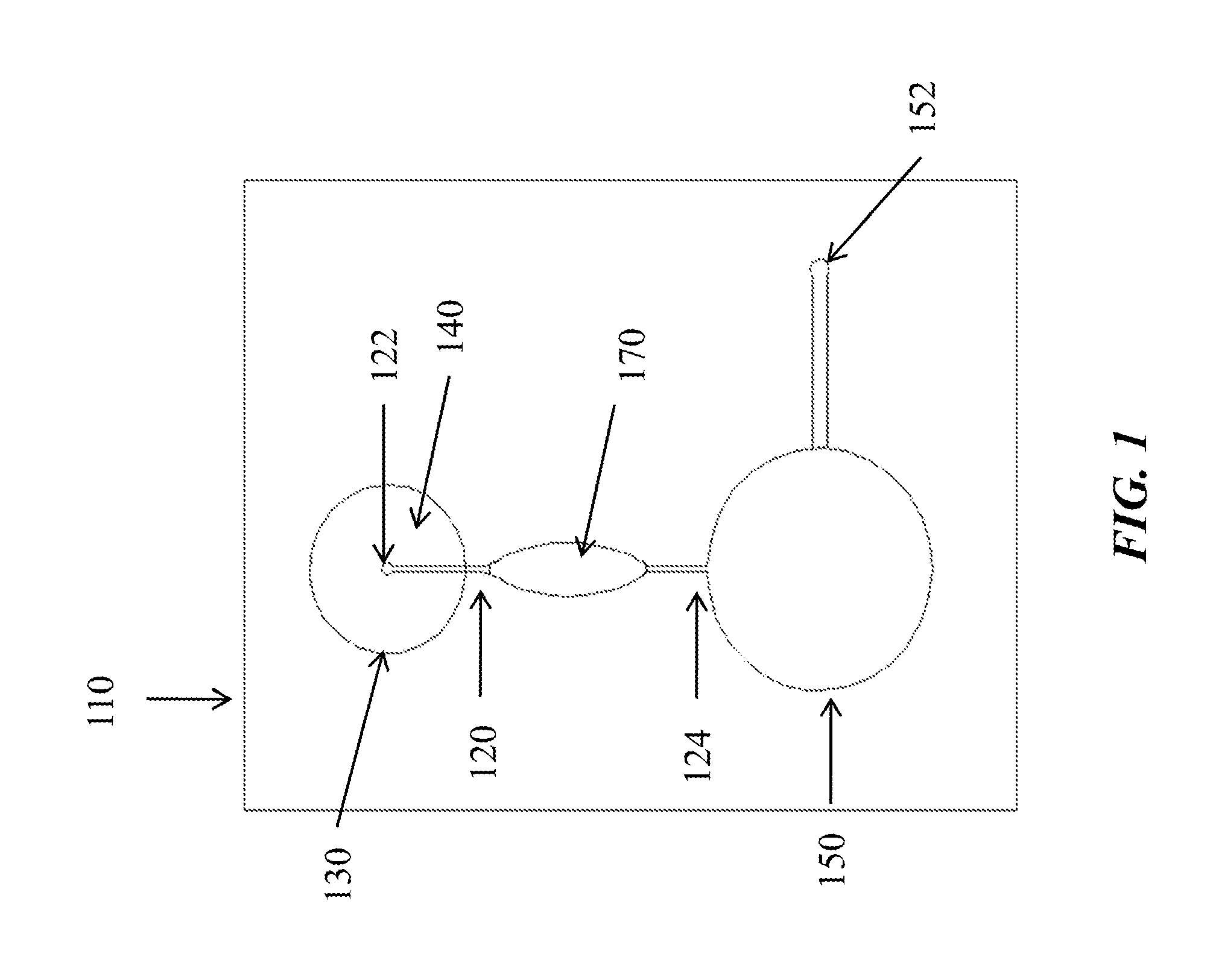
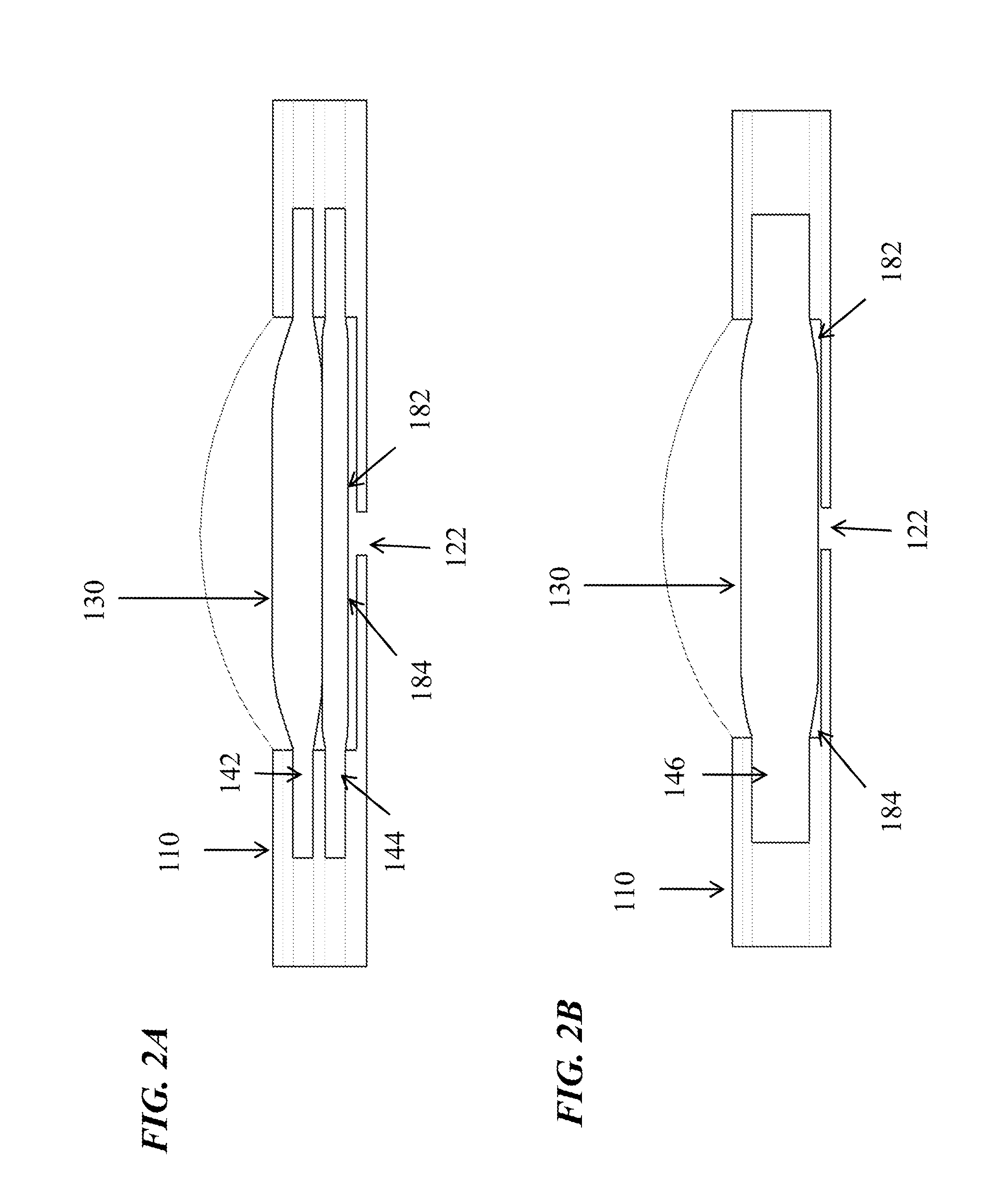
The present invention provides a microfluidic device that can be used for various applications such as separating serum from blood samples and cross-matching donor and recipient samples. The device includes a microfluidic channel with a composite membrane interposed between the sample inlet and the channel, which can activate blood coagulation and remove selected particles from the blood. An optional on-device pump can be connected to the channel for controlled fluid flow. The device also includes a solute mixing subcircuit with a critical length for enabling solute mixture by diffusion, a downstream channel with a width greater than the mixing channel, and a pump for initiating fluid flow. The composite membrane can include at least two membranes or a glass filter and an activator of blood coagulation. The methods for using the microfluidic device for separation and cross-matching are also provided.

Problems solved by technology

Serum samples are separated from whole blood before analysis to remove red blood cells and clotting factors, which have the potential to interfere with cross-match agglutination reactions, colorimetric tests, as well as contribute to hematocrit-dependent variations amongst samples.
The conventional method of serum separation, requiring sample centrifugation, is obviously not amenable to microscale adaptation.
Serious consequences such as kidney failure or splenic rupture can result from a transfusion of mismatched blood.
Currently, medical technicians in the field do not have access to a simple and accurate means of evaluating a donor and recipient pair for possible transfusion reactions during emergency medical treatment, for example, during military operations.
Tube agglutination assays are currently used prior to blood transfusion, however these assays are cumbersome and involve erythrocyte preparation and long incubation times. These assays may not always lead to consistent results depending upon the experience of the technician.
Additionally, some technicians do not have access to a laboratory qualified to perform agglutination assays.

Method used


Image

  • Microfluidic devices and methods for performing serum separation and blood cross-matching
  • Microfluidic devices and methods for performing serum separation and blood cross-matching
  • Microfluidic devices and methods for performing serum separation and blood cross-matching

Examples


example 1

Assessment of Glass Fiber Filters in Promoting Blood Coagulation

[0065]This example demonstrates that glass fiber filters promote blood coagulation on a microfluidic device.

[0066]Various borosilicate glass fiber filters as set forth in Table 1 were stacked with the Pall Vivid GR membrane and laminated into “cartridges” (i.e., into a microfluidic device) using standard construction methods known in the art. For testing, 100 μL of fresh, whole blood was applied to the filter and allowed to clot for up to 15 minutes. Liquid sample was pulled by vacuum into a collection chamber. Performance of the filters was evaluated based on the volume of serum obtained in one minute and on the color of the serum. As shown in Table I, several of the glass fiber filters tested enabled on-card serum separation. Pink serum indicates that some degree of hemolysis has occurred. These results indicate that serum separation can, surprisingly, be achieved on-card (i.e., within a microfluidic device) by incorp...

example 2

Design of a Microfluidic Subcircuit for Serum Separation

[0068]This example demonstrates serum separation by a microfluidic device incorporating a glass fiber, composite filter.

[0069]A microfluidic subcircuit with a collection chamber and a port was designed to separate serum from a whole blood sample. Fresh, whole finger-stick collected blood (approximately 200 μL) was applied to a composite filter as described above and allowed to clot. In operation, the user's index finger compresses a finger pump, while a second finger covers the vent holes. The vacuum generated when the index finger is removed pulls the sample through the filters into the collection chamber. The filtered sample was collected using a mechanical pipettor with a disposable tip. The recovered material was characterized as serum by measurement of the residual fibrinogen content. Plasma contains fibrinogen, while serum is depleted of this protein due to activation of the clotting cascade, during which fibrinogen is co...


PUM

PropertyMeasurementUnit
sizesaaaaaaaaaa
pore sizeaaaaaaaaaa
diameteraaaaaaaaaa

Abstract

Microfluidic cartridges or devices for serum separation and blood cross-match analysis are provided. The devices may include a serum separation subcircuit alone or in combination with a solute mixing subcircuit. The serum separation subcircuit promotes on-cartridge clotting of a blood sample and manipulates the flow of the separated serum sample for subsequent cross-match analysis with a second blood sample, for example. The solute mixing subcircuit includes at least two intake channels, one for a whole blood sample from, for example, a blood donor and the other for the separated serum sample from, for example, a transfusion recipient. The solute mixing subcircuit further includes a serpentine mixing channel conjoined to a downstream channel. Under vacuum generated by a conjoined finger pump, the two input streams fill the serpentine mixing and downstream channels due to capillary action, enabling visualization of an agglutination reaction.

Description

BACKGROUND[0001]1. Technical Field[0002]This invention generally pertains to devices, apparatus, and methods for separation of serum from whole blood and potentiation of agglutination reactions in microfluidic devices. Agglutination reactions involving antigen:antibody reactions are useful in cross-matching for blood transfusion.[0003]2. Description of the Related Art[0004]Analysis of blood prior to transfusion or for clinical assessments relies on diagnostic devices, such as cross-matching or blood-typing devices, and blood chemistry monitors that measure metabolites such as glucose or cholesterol. Such devices must frequently use serum, the uncolored fluid portion of the blood containing analytes of interest to clinicians. Serum samples are separated from whole blood before analysis to remove red blood cells and clotting factors, which have the potential to interfere with cross-match agglutination reactions, colorimetric tests, as well as contribute to hematocrit-dependent variati...

Claims


Application Information

Patent Timeline
Patent Type & Authority Applications(United States)
IPC IPC(8): G01N33/80B01L3/00
CPCG01N33/80B01L3/502715B01L3/50273B01L3/502753B01L2200/10B01L3/502723B01L2300/0883B01L2300/0681B01L3/502738B01L2200/027B01L2300/0816B01L2400/0406B01L2400/0481G01N33/491B01L3/502761B01L2300/0867B01L2300/163G01N33/86
Inventor KOLB, ANDREW W.ELMUFDI, CAROLINA L.BATTRELL, C. FREDERICK
Owner PERKINELMER HEALTH SCIENCES INC
Learn More