Method for producing infrared radiation reflecting film

a technology of infrared radiation and reflecting film, which is applied in the direction of instruments, optical elements, vacuum evaporation coating, etc., can solve the problems of insufficient physical strength of metal oxide layers, increased emissivity, and inability to achieve heat insulating effects, etc., to achieve enhanced adhesion between metal layers and metal oxide layers, the effect of increasing the deposition rate of metal oxide layers and increasing the productivity of infrared reflecting films

Inactive Publication Date: 2016-05-26
NITTO DENKO CORP
View PDF1 Cites 7 Cited by
  • Summary
  • Abstract
  • Description
  • Claims
  • Application Information

AI Technical Summary

Benefits of technology

[0019]In the present invention, since ZTO is deposited on the metal layer by DC sputtering method using a specific target, a deposition rate of the metal oxide layer is increased, and therefore the productivity of the infrared reflecting film can be increased. Moreover, the adhesion between the metal layer and the metal oxide layer is enhanced by depositing ZTO by a specific oxygen introduction amount. According to the manufacturing method of the present invention, it is possible to deposit a ZTO metal oxide layer, having excellent durability, with high adhesion on the metal layer composed mainly of silver. Therefore, an infrared reflecting film having high durability is obtained even when a thickness of the transparent protective layer is small.
[0020]Further, since the metal oxide layer is formed on the metal layer without forming a primer layer, visible light transmittance of the infrared reflecting film is increased and an improvement of the productivity by virtue of a reduction in the number of stacked layers in the infrared reflecting layer is expected. Moreover, by increasing an oxygen introduction amount in substrate-side metal oxide layer forming step, a visible light transmittance of the infrared reflecting substrate tends to be increased.

Problems solved by technology

These metal layers and metal oxide layers do not have sufficient physical strength such as abrasion-resistance and tend to cause deterioration due to external environment factors such as heat, ultraviolet ray, oxygen and water.
Therefore, when an amount of the far-infrared rays absorbed by the protective layer is large, the emissivity is increased and the heat insulating effect is not achieved.
On the other hand, when the thickness of the protective layer is decreased, a protecting effect by the protective layer is decreased and therefore the durability of the infrared reflecting layer, particularly, the metal layer tends to deteriorate.
In general, if the metal layer is oxidized, the far-infrared absorptivity (emissivity) increases, and this tends to cause deterioration of heat insulating properties or a reduction of the visible light transmittance.
Further, a metal oxide layer constituting the infrared reflecting layer generally has insufficient adhesion to a metal layer such as silver, and this is also a factor of deteriorating the durability of the infrared reflecting layer.
However, in order to deposit the metal primer layer between the metal oxide layer and the metal layer, facilities are complicated due to an increase of number of deposition targets used and number of times of deposition for forming an infrared reflecting layer, and this causes a reduction of productivity.
Further, low visible light transmittance of the metal such as Ni—Cr may cause a problem of reduction of a visible light transmittance of the infrared reflecting substrate.

Method used


Image

  • Method for producing infrared radiation reflecting film
  • Method for producing infrared radiation reflecting film
  • Method for producing infrared radiation reflecting film

Examples


example 1

[0114](Formation of Hard Coat Layer on Substrate)

[0115]An acryl-based ultraviolet-curable hard coat layer (manufactured by Nippon Soda Co., Ltd., NH2000G) was formed in a thickness of 2 μm on one surface of a polyethylene terephthalate film (manufactured by Toray Industries Inc., trade name “Lumirror U48”, visible light transmittance 93%) having a thickness of 50 μm. Specifically, a hard coat solution was applied with a gravure coater, dried at 80° C., and irradiated with ultraviolet rays of accumulated light quantity of 300 mJ / cm2 by an ultra high pressure mercury lamp to be cured.

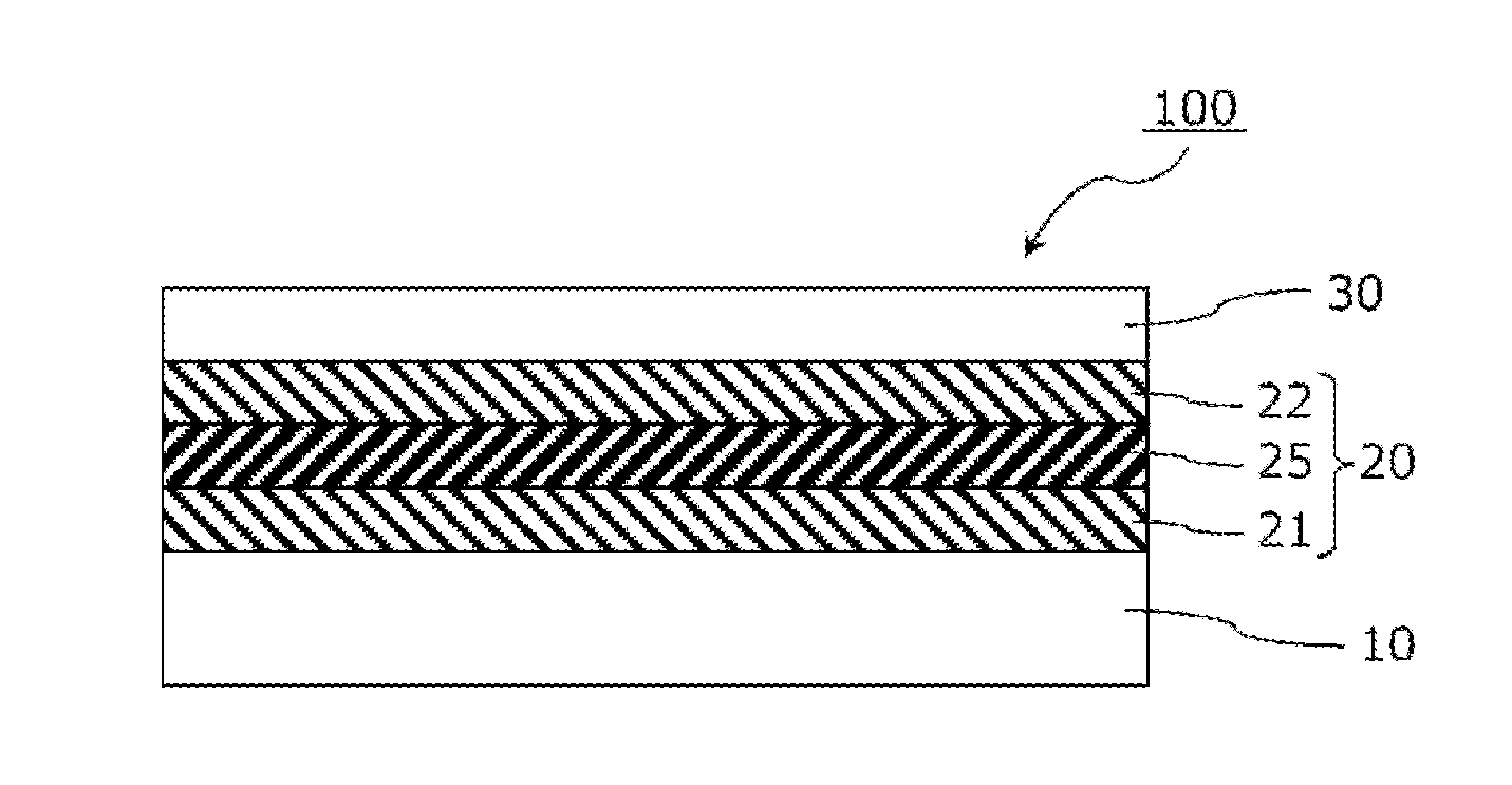
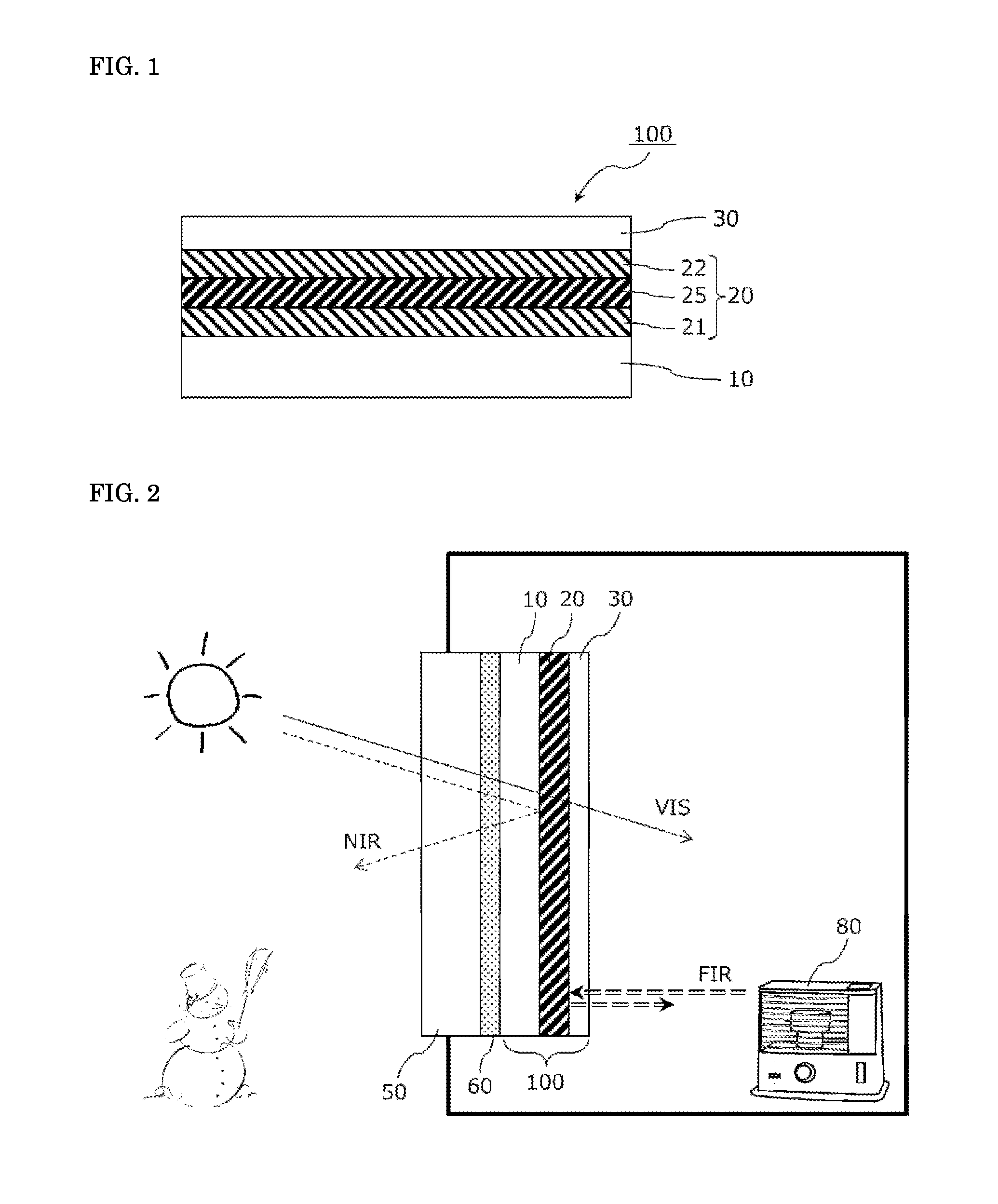
[0116](Formation of Infrared Reflecting Layer)

[0117]An infrared reflecting layer was formed on a hard coat layer of the polyethylene terephthalate film substrate by using a roll-to-roll sputtering apparatus. Specifically, by a DC magnetron sputtering method, a substrate-side metal oxide layer composed of a zinc-tin composite oxide (ZTO) and having a thickness of 30 nm, a metal layer composed of an Ag—Pd a...

examples 2a and 2b

[0120]The amount of gas introduced into the sputtering chamber in deposition of the substrate-side metal oxide layer was changed so that a volume ratio between Ar and O2 is 90:10 (Example 2A) and a volume ratio between Ar and O2 is 95:5 (Example 2B). The amount of Ar gas / O2 gas introduced in deposition of the surface-side metal oxide layer was set so that a volume ratio between Ar and O2 is 98:2 as with Example 1. Infrared reflecting films were prepared in the same manner as in Example 1 except for changing the amount of gas introduced in deposition of the substrate-side metal oxide layer as described above.

example 3

[0121]As the sputtering target for forming the substrate-side metal oxide layer and the surface-side metal oxide layer, a target formed by sintering composition consisting of zinc oxide, tin oxide, and a metal zinc powder at a weight ratio of 19:73:8 was used. In the same manner as in Example 1 except for this, an infrared reflecting film was prepared.


PUM

PropertyMeasurementUnit
wavelengthaaaaaaaaaa
visible light transmittanceaaaaaaaaaa
thicknessaaaaaaaaaa

Abstract

The method for manufacturing an infrared reflecting film comprises, in order: a metal layer forming step of depositing a metal layer on a transparent film substrate; a metal oxide layer forming step of depositing a surface-side metal oxide layer by DC sputtering on the metal layer so as to be in direct contact with the metal layer; and a transparent protective layer forming step of depositing a transparent protective layer on the surface-side metal oxide layer. In the metal oxide layer forming step, a sputtering target used for DC sputtering contains zinc atoms and tin atoms, and is preferably formed by sintering a metal powder and at least one metal oxide among zinc oxide and tin oxide. In the surface-side metal oxide layer forming step, an inert gas and an oxygen gas are introduced into a sputtering chamber. The oxygen concentration in the gas introduced to the sputtering chamber is preferably not more than 8 vol %.

Description

TECHNICAL FIELD[0001]The present invention relates to a method for manufacturing an infrared reflecting film which is mainly used for arranging on an interior side of glass windows or the like.BACKGROUND ART[0002]Heretofore, an infrared reflecting substrate having an infrared reflecting layer on a substrate of glass, film or the like is known. As the infrared reflecting layer, an alternative laminate of metal layer(s) and metal oxide layer(s) is widely used. The infrared reflecting layer can have a heat shielding property by reflecting near-infrared rays such as sunlight. As the metal layer, silver or the like is widely used from the viewpoint of enhancing the selective reflectivity of infrared rays, and as the metal oxide layer, an indium-tin composite oxide (ITO) or the like is widely used. These metal layers and metal oxide layers do not have sufficient physical strength such as abrasion-resistance and tend to cause deterioration due to external environment factors such as heat, ...

Claims


Application Information

Patent Timeline
Patent Type & Authority Applications(United States)
IPC IPC(8): C23C14/34C23C14/08C23C14/20
CPCC23C14/3464C23C14/086C23C14/205C23C14/3414G02B5/282G02B5/285B32B2307/416B32B17/10
Inventor WATANABE, MASAHIKOOHMORI, YUTAKA
Owner NITTO DENKO CORP
Why Eureka
Try Eureka