
Electrode winding element for non-aqueous electrolyte rechareable battery, non-aqueous electrolyte rechargeable lithium battery including same, method of preparing same

Active Publication Date: 2016-06-23
SAMSUNG SDI CO LTD
View PDF6 Cites 3 Cited by
  • Summary
  • Abstract
  • Description
  • Claims
  • Application Information

AI Technical Summary

Benefits of technology

The patent text describes an improved design for a battery electrode wound element that can improve the handling of a separator during manufacturing, prevent deformation, and enhance the adhesion of the separator to each electrode. This design can also improve the cycle expansion of the battery and provide better performance overall.

Problems solved by technology

However, the separator having the PVDF porous layer on the surface in the above method has insufficient slipperiness when compared to a separator having no porous layer and easily becomes electrostatic and thus is difficult to handle in a preparing process.
Specifically, when the separator is overlapped with belt-shaped positive and negative electrodes for a wound element, the wound element becomes deformed due to the insufficient mutual slipperiness of the separator.
When the wound element is deformed, the wound element is difficult to be inserted into a case.
In addition, a non-aqueous electrolyte rechargeable battery using this deformed wound element may have an insufficient cycle-life.
Furthermore, the separator having the polyvinylidene fluoride porous layer on the surface according to the aforementioned method has insufficient adherence to an electrode, and particularly, the insufficient adherence problem tends to be severe when the separator includes a heat resistance filler to improve heat resistance.
When the separator has insufficient adherence to each electrode, a wound element may has a problem of easy expansion (so-called a problem of cycle expansion) as charge and discharge proceed.
However, these methods do not solve the aforementioned problem at all.

Method used


Image

  • Electrode winding element for non-aqueous electrolyte rechareable battery, non-aqueous electrolyte rechargeable lithium battery including same, method of preparing same
  • Electrode winding element for non-aqueous electrolyte rechareable battery, non-aqueous electrolyte rechargeable lithium battery including same, method of preparing same
  • Electrode winding element for non-aqueous electrolyte rechareable battery, non-aqueous electrolyte rechargeable lithium battery including same, method of preparing same

Examples


example 1

Preparation of Positive Electrode

[0108]Lithium cobalt oxide, carbon black, and polyvinylidene fluoride (PVDF) in a solid weight ratio of 96:2:2 were dissolved in and dispersed in N-methyl pyrrolidone, preparing positive active material layer slurry.

[0109]The positive active material layer slurry was coated on both sides of a 12 μm-thick aluminum foil as a current collector, dried, and compressed, forming a positive active material layer. The current collector and the positive active material layer had a total thickness of 120 μm. Subsequently, an aluminum lead wire was welded at the terminal end of the electrode, obtaining a belt-shaped positive electrode.

Preparation of Negative Electrode

[0110]On the other hand, negative active material layer slurry was prepared by dissolving and dispersing graphite, a modified SBR particulate aqueous dispersed material, a fluorine resin-containing particulate aqueous dispersed material complicated by polymerizing an acrylic resin in polyvinylidene ...

example 2

[0126]The adhesive layer mix slurry was prepared by dissolving and dispersing the fluorine resin-containing particulate aqueous dispersed material of Example 1, poly-N-vinyl acetamide, a cross-linked poly methylmethacrylate particle (PMMA), and a boehmite particle in and into water as a solvent. Herein, the poly-N-vinyl acetamide is a binder for an adhesive layer. In addition, the cross-linked poly methylmethacrylate particle and the boehmite particle are a heat resistance filler. The cross-linked poly methylmethacrylate particle and the boehmite particle are mixed in a volume ratio of 50:50. In addition, the fluorine resin-containing particulate, the binder for an adhesive layer, and the heat resistance filler were mixed in a volume ratio of 45:4:51. Then, a battery cell was prepared according to the same method as Example 1 except for using the adhesive layer mix slurry.

example 3

[0127]The fluorine resin-containing particulate aqueous dispersed material according to Example 1, polyvinylpyrrolidone, carboxylic acid-modified polybutyl acrylate, a cross-linked poly methylmethacrylate particle, and an alumina particle were dissolved and dispersed in and into water as a solvent, preparing adhesive layer mix slurry. Herein, the polyvinylpyrrolidone and the carboxylic acid-modified butyl acrylate were mixed in a ratio of 1:5 as a binder for an adhesive layer. In addition, the cross-linked poly methylmethacrylate particle and the alumina particle were mixed in a volume ratio of 30:70 as a heat resistance filler. Furthermore, the fluorine resin-containing particulate, the binder for an adhesive layer, and the heat resistance filler were mixed in a volume ratio of 44:6:50. A battery cell was prepared according to the same method as Example 1 except for using the adhesive layer mix slurry.


PUM


Abstract

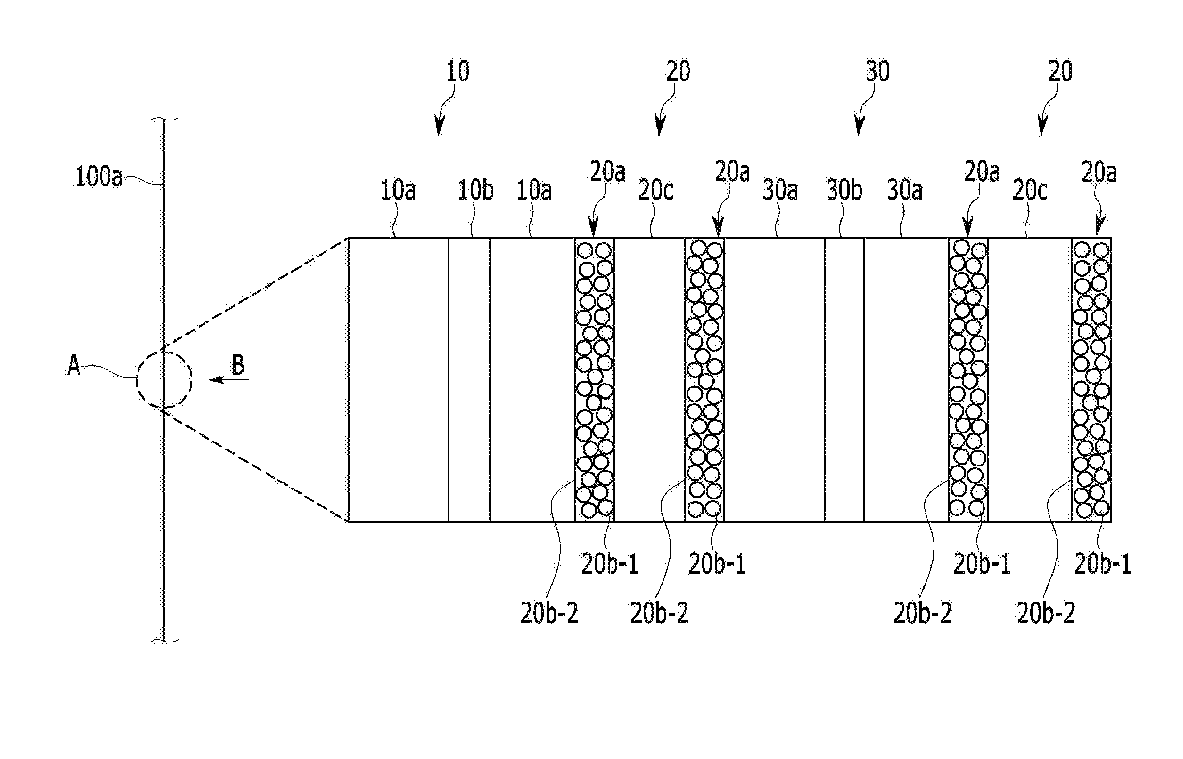
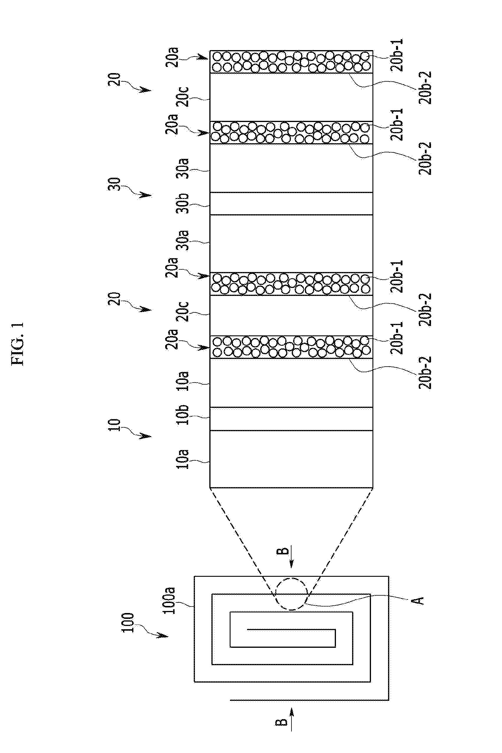
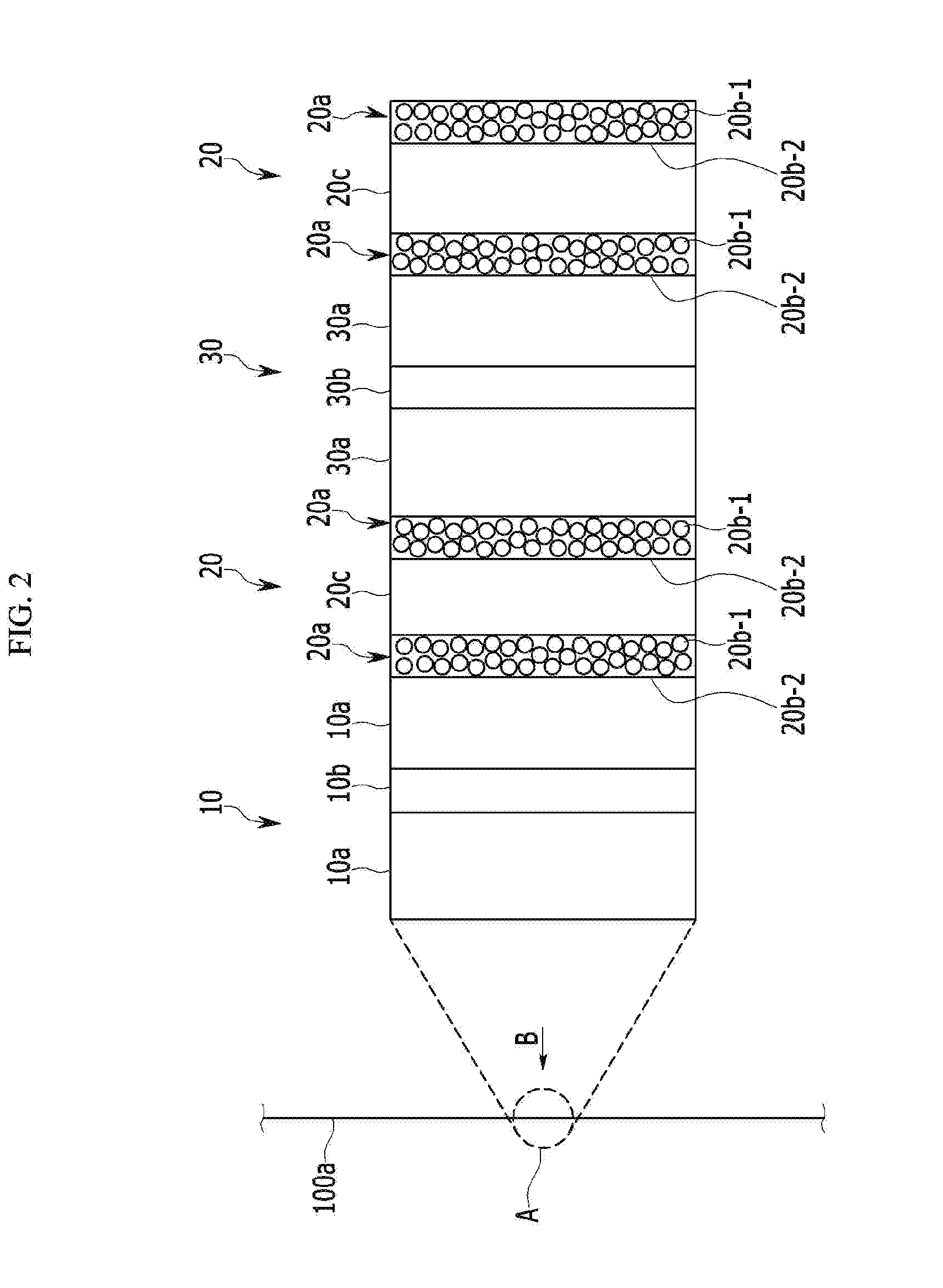
An electrode wound element for a non-aqueous electrolyte rechargeable battery includes a belt-shaped positive electrode; a belt-shaped negative electrode; a belt-shaped porous layer between the belt-shaped positive electrode and the belt-shaped negative electrode; and an adhesive layer formed on the surface of the belt-shaped porous layer, wherein the adhesive layer includes a fluorine resin-containing particulate and a binder for an adhesive layer supporting the fluorine resin-containing particulate, the binder comprising at least one of an ionic non-water-soluble binder, a non-ionic water-soluble binder, a non-ionic non-water-soluble binder and an ionic water-soluble binder.

Description

INCORPORATION BY REFERENCE TO RELATED APPLICATIONS[0001]Any and all priority claims identified in the Application Data Sheet, or any correction thereto, are hereby incorporated by reference under 37 CFR 1.57. This application claims priority to and the benefit of Japanese Patent Application No. 2014-258189 filed in the Japanese Patent Office on Dec. 22, 2014, and Korean Patent Application No. 10-2015-0117519 filed in the Korean Intellectual Property Office on Aug. 20, 2015. Each of the aforementioned applications is incorporated by reference herein in its entirety, and each is hereby expressly made a part of this specification.BACKGROUND[0002]1. Field[0003]An electrode wound element for a non-aqueous electrolyte rechargeable battery, a non-aqueous electrolyte rechargeable battery including the same, and a method of preparing the electrode wound element for a non-aqueous electrolyte rechargeable battery are provided.[0004]2. Description of the Related Art[0005]Research on a polyvinyl...

Claims


Application Information

Patent Timeline
IPC IPC(8): H01M4/62H01M10/0525H01M10/04H01M4/139H01M50/403H01M50/426
CPCH01M4/623H01M4/139H01M2004/029H01M4/622H01M10/0431H01M10/0525H01M10/0587H01M50/461H01M50/403H01M50/426H01M10/052Y02E60/10Y02P70/50H01M4/62
Inventor HOSHIBA, KOJI
Owner SAMSUNG SDI CO LTD
Learn More