

Method and apparatus for measuring surface properties of polishing pad
a technology of surface properties and polishing pads, applied in the direction of lapping machines, instruments, abrasive surface conditioning devices, etc., can solve the problems of deterioration of polishing performance, poor film coating performance (step coverage), and large steps, so as to reduce the cost of consumable materials
- Summary
- Abstract
- Description
- Claims
- Application Information
AI Technical Summary
Benefits of technology
Problems solved by technology
Method used
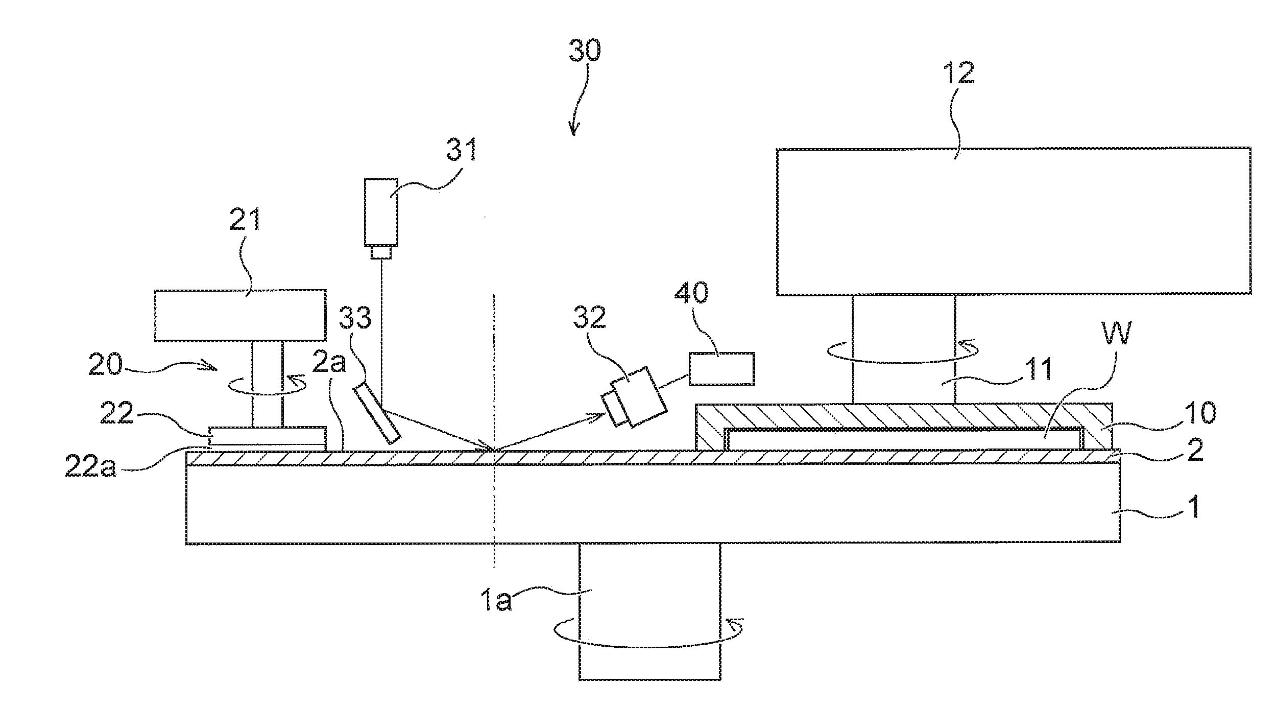
Image

Examples
first embodiment
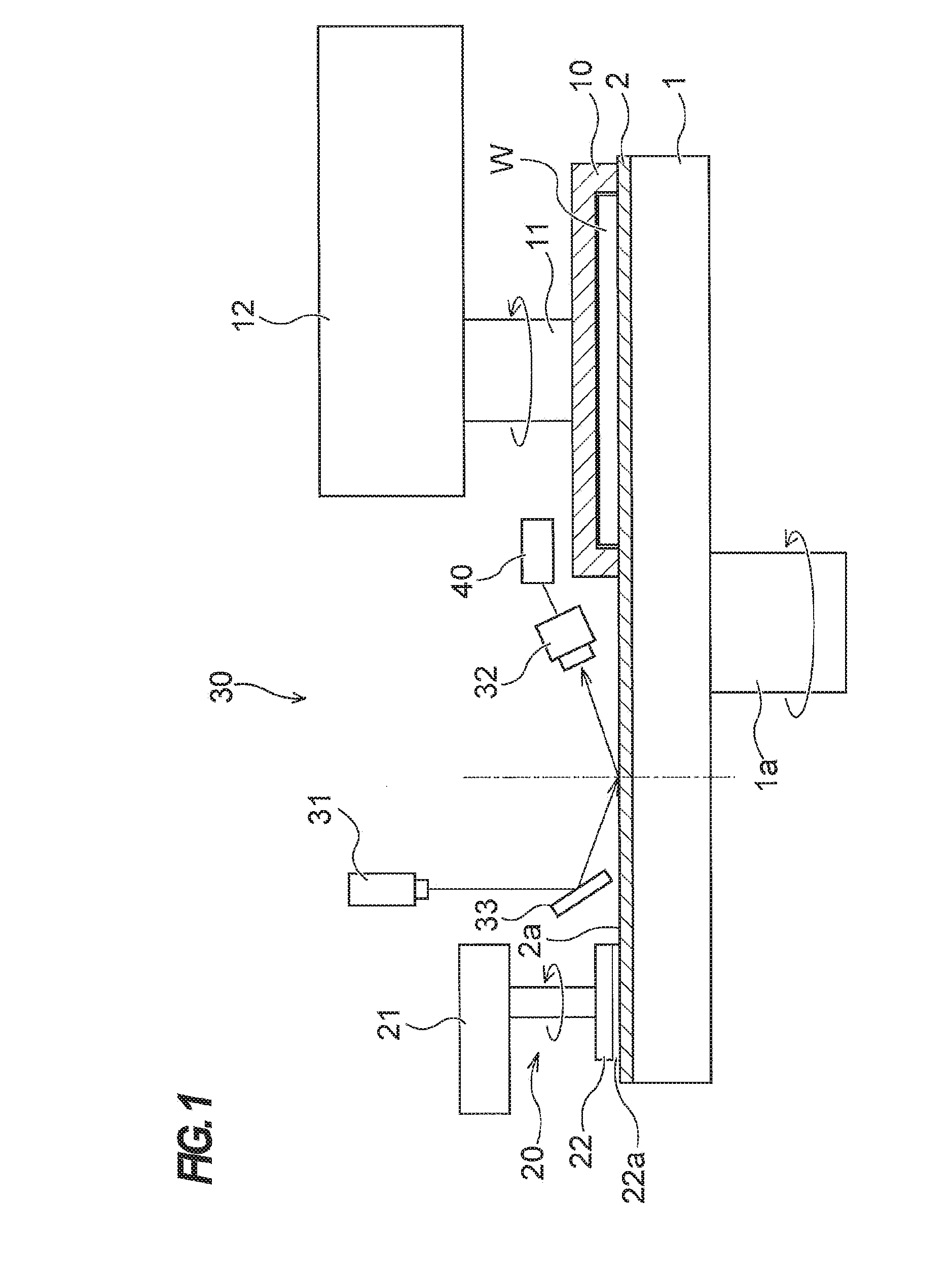
[0057]FIG. 2 is a schematic front elevational view showing the polishing pad surface property measuring apparatus 30. In the surface property measuring apparatus 30 shown in FIG. 2, the light source 31 is fixed in position, and the mirror 33 and the light receiver 32 are vertically movable. As shown in FIG. 2, the mirror 33 is movable between a lowered position indicated by the solid lines and an elevated position indicated by the two-dot chain lines. Further, the light receiver 32 is movable between a lowered position indicated by the solid lines and an elevated position indicated by the two-dot chain lines.
[0058]In the polishing pad surface property measuring apparatus 30 that is arranged as shown in FIG. 2, when both the mirror 33 and the light receiver 32 are in the lowered position indicated by the solid lines, the laser beam emitted from the light source 31 is reflected by the mirror 33 to change its optical path and is then applied to the polishing pad at an incident angle=A....
second embodiment
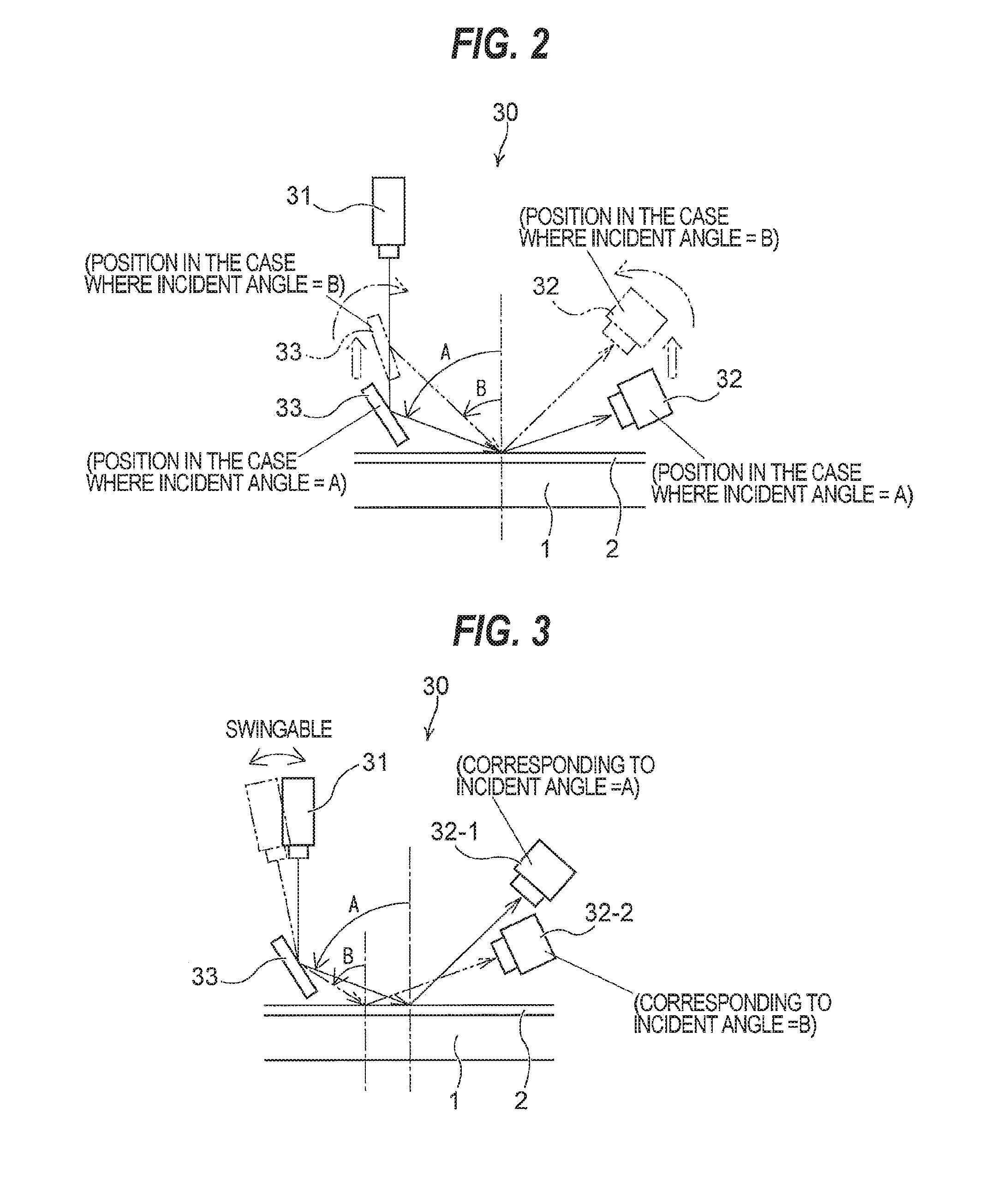
[0061]FIG. 3 is a schematic front elevational view showing the polishing pad surface property measuring apparatus 30. In the polishing pad surface property measuring apparatus 30 shown in FIG. 3, the mirror 33 and the light receiver 32 are fixed in position, and the light source 31 is configured to be movable, i.e., swingable. As shown in FIG. 3, the light source 31 is configured to be swingable between a vertical position indicated by the solid lines and a tilted position indicated by the two-dot chain lines. Further, there are provided two light receivers comprising a first light receiver 32-1 disposed in an upper position and a second light receiver 32-2 disposed in a lower position.
[0062]In the polishing pad surface property measuring apparatus 30 that is arranged as shown in FIG. 3, when the light source 31 is in the vertical position indicated by the solid lines, the laser beam emitted from the light source 31 is reflected by the mirror 33 to change its optical path and is the...
third embodiment
[0065]FIG. 4 is a schematic front elevational view showing the polishing pad surface property measuring apparatus 30. In the polishing pad surface property measuring apparatus 30 shown in FIG. 4, the mirror 33 and the light receiver 32 are fixed in position, and the light source 31 is configured to be movable, i.e., swingable. As shown in FIG. 4, the light source 31 is configured to be swingable between the vertical position indicated by the solid lines and the tilted position indicated by the two-dot chain lines. The light receiver 32 has a light receiving surface 32a for receiving the reflected light, and the light receiving surface 32a is set to be greater than the light receiving surfaces of the light receivers shown in FIGS. 2 and 3. Therefore, the light receiver 32 is capable of receiving the reflected light even when reflection angles of the reflected light from the polishing pad 2 differ.
[0066]In the polishing pad surface property measuring apparatus 30 that is arranged as s...
PUM
| Property | Measurement | Unit |
|---|---|---|
| incident angles | aaaaa | aaaaa |
| incident angles | aaaaa | aaaaa |
| Brewster angle | aaaaa | aaaaa |
Abstract
Description
Claims
Application Information