Media Control Valve

a control valve and media technology, applied in the field of media control, can solve the problems of not allowing the plunger to reciprocate within the spool, affecting the operation of the valve, and damage to the valve beyond use, so as to facilitate maintenance and repair, reduce or even eliminate the tendency of various components to bind during operation, and ensure the proper alignment of the various components

Inactive Publication Date: 2016-07-07
NGUYEN PHUONG TAYLOR
View PDF11 Cites 8 Cited by
  • Summary
  • Abstract
  • Description
  • Claims
  • Application Information

AI Technical Summary

Benefits of technology

[0029]It is an important feature of the valve of the subject invention that the rigid assembly between components which is common in the prior art valves has been replaced with a floating design with components being assembled using numerous resilient seals and spacers between rigid members, permitting the assembly to self-center or self-position. This minimizes or even eliminates the tendency of various components to bind during operation, particularly as a result of normal operation and normal wear. This also assures proper alignment of the various components by permitting relative movement between components during operation. The floating design of the subject invention also facilitates in maintenance and repair by permitting the assembly to be disassembled by relying on the relative ease in removing the resilient seals.
[0030]Even in prior art designs having a single plunger seal, the spool/sleeve design of the subject invention will allow for additional space to include additional plunger seals or wipers which will improve the life and versatility of these valves, as well. Also, the addition of a properly aligned wiper immediately above the sleeve orifice keeps all the grit between hard-to-hard surfaces, thus reducing sliding friction and preventing the accumulation of residual grit between the plunger and spool. This also reduces the size of the grit that can migrate past the wiper seals.
[0031]In yet another aspect of the invention, the composite spool may incorporate a soft urethane or equivalent material to encapsulate a hard abrasion resistant material such as tungsten carbide or hardened stainless steel. The softer thermoplastic spool will allow for easy removal while the hard liner or sleeve will provide longevity, durability and low friction. Revising the cavity to have a taper allows the gap relative to the spool to increase during extraction or removal thus decreasing the bind and rolling and allow the spool to release easily. In addition, a taper, at the same angle as the mating inside surface of the body cavity, can be utilized. This will further ease the release of the spool from the body.
[0032]The modular plunger design of the subject invention utilizes fasteners to fix a hardened (example: tungsten carbide) jacket around the softer (example: stainless) plunger core. In this design, the tungsten carbide slides over the stainless with three seals between them and held in place with a bolt screwed into the stainless shaft. The tungsten jacket can be removed and replaced onto the stainless plunger core. This reduces the cost of the replacement part by reusing the stainless plunger core or shaft. In addition, the two o-rings a

Problems solved by technology

One of the most critical issues with remote actuated media control valves is the life of the valve.
The abrasive media can damage the valve beyond use in a short period of time, requiring replacement or substantial repair.
It is not uncommon for any of these valves to malfunction after some use due to the spool and plunger locking up, thereby not allowing the plunger to reciprocate within of the spool.
In either case when plungers lock up or seize, accelerated wear results on the adjacent components of the valve such as the body, seat, and base.
However, this patent does not address the more frequent mode of failure where the plunger binds against the spool, or is seized.
While these designs have been effective at sealing, there are two issues.
In many of these valves it is very difficult to change out the seals due to the deep location of the seals with the inherently gritty environment.
In valves utilizing the multiple plunger seal design, the plunger seals are stacked on top of each other which is a blind install that does not permit visual verification of proper seal alignment or seal installation.
Also, this will create boundaries where two soft surfaces press against each other, which creates an opportunity for the seals to misalign when stressed during plunger movement or during installation or operation.
First, the stainless sleeve on the spool wears at the ID more quickly than at the hard jacket primarily because of the difference in hardness of the two materials.
These harder particles can dig into the relatively softer yet still rigid stainless steel and cause binding between the plunger and spool.
Third, this design permits the accumulation of grit within the plunger-to-spool gap.
This is a problem with all plunger-spool designs in the air blast industry regardless of their hardness and regardless of their material composition.
Recently, valve designs including an offset spool internal diameter and plunger seals of

Method used


Image

  • Media Control Valve
  • Media Control Valve
  • Media Control Valve

Examples


Embodiment Construction

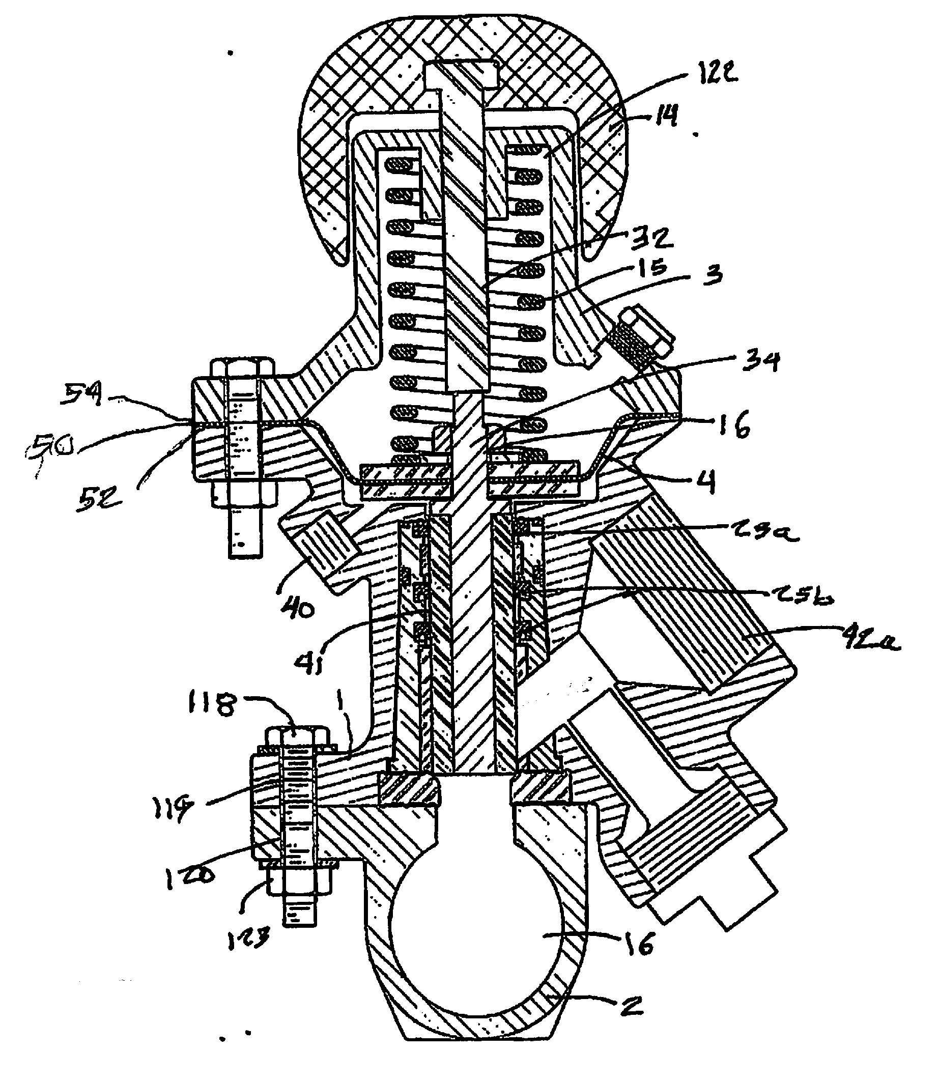
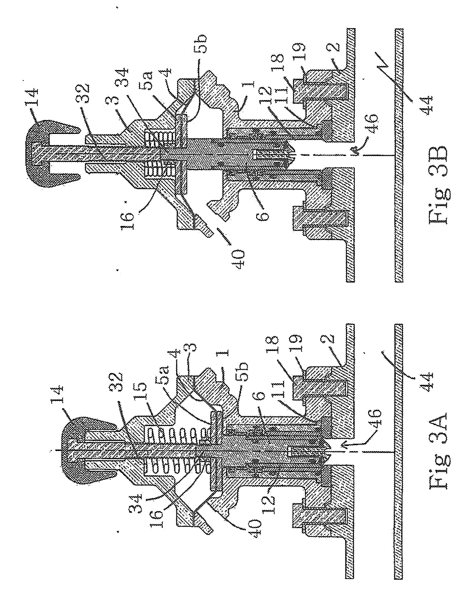
[0047]The plunger and bore assembly in the lower valve body are substantially different from prior art assemblies and for sake of clarity and consistency the following terms are used throughout this application when referring to the plunger assembly and the bore or body cavity components in the valve body:

[0048]Valve body 1, which houses the valve plunger assembly, the spool assembly and the lower diaphragm plate.

[0049]Plunger 6, this is an assembly and comprises the plunger stem 34, the plunger 6, the plunger jacket 7 on the exterior of the plunger 6 and the various seals 8, 20 (FIG. 5a) mounted on the plunger or jacket. The plunger assembly may include a washer or seating ring 10 and a retaining screw or fastener 17 or other securement means for holding the plunger assembly including the sleeve, seals and seating ring in assembled relationship.

[0050]Body cavity 76 (FIGS. 4, 6, 7 and 9, for example) is the central internal cavity of the valve body and houses spool 11 and the spool ...


PUM


Abstract

A media control valve includes a body, a plunger assembly of multiple components housed in the body with a plunger control valve cap assembly secured to the body for housing a control knob. The body and the plunger assembly include resilient seals between adjacent multiple components of the body and the plunger assembly, respectively, to permit relative movement therebetween during assembly and use. The media control valve includes a diaphragm which acts as a membrane that physically isolates and seals the chambers above and below. The spool design of the valve has all of the seals and bushings held within the spool. Once the spool is removed, the replacement seals and bushings can be replaced and inspected with relative ease due to the accessibility at both ends of the spool. Since each plunger seal is held within its own rigid cavity, held on three sides and not stacked on top of another seal or loose component, proper alignment is better assured during and after installation. The body components parts are also assembled using resilient seals to facilitate assembly and repair, while reducing any tendency of the valve to seize during use.

Description

REFERENCE TO RELATED APPLICATIONS[0001]Reference to related Applications. This application is a continuation-in-part of the U.S. patent application Ser. No.: 13 / 286,206, entitled “Modular Control Valve” filed on Oct. 31, 2011, now U.S. Pat. No.: 8,827,243 issued Sep. 9, 2014, and a continuation-in-part of copending U.S. patent application Ser. No.: 14 / 177,224, filed on Feb. 11, 2014, which is also a continuation-in-part of U.S. patent application Ser. No.: 13 / 286,206. Said applications are fully incorporated by reference herein. Full priority to the filing date of Oct. 31, 2011, as applicable to previously disclosed material therein is claimed herein.BACKGROUND[0002]1. Field of the Invention[0003]The present invention is related to media control and more specifically, media control valves used to control the flow of a media into a fluid stream as part of an apparatus for treatment of a surface.[0004]2. Description of the Related Art[0005]A typical manual media control valve is discl...

Claims


Application Information

Patent Timeline
IPC IPC(8): F16K1/32F16K3/24
CPCF16K3/246F16K1/32F16K31/145F16K1/10F16K31/1262F16K27/041
Inventor NGUYEN, PHUONG TAYLOR
Owner NGUYEN PHUONG TAYLOR
Why Eureka
Try Eureka