
High Thermal Efficiency Six Stroke Internal Combustion Engine with Heat Recovery

a heat recovery and internal combustion engine technology, applied in the field of internal combustion engine recuperation, can solve problems such as quiet engines, and achieve the effects of reducing heat loss, high efficiency, and increasing the work output of the engin

Active Publication Date: 2016-08-25
JUNG PHILIP OWEN
View PDF9 Cites 7 Cited by
  • Summary
  • Abstract
  • Description
  • Claims
  • Application Information

AI Technical Summary

Benefits of technology

The patent text discusses various methods to improve the thermal efficiency of IC engines. These include turbocharging, supercharging, recycling heat, reducing exhaust pressure, and other techniques. The text also mentions the development of variable valve timing, camless valve operation, and cylinder deactivation. However, the improvements need to happen faster. The invention described in this patent aims to achieve a shift in thermal efficiency and a reduction in emissions.

Problems solved by technology

This thermal insulation also captures engine noise, thus resulting in a quiet engine.
The flow of superheated steam must be controlled due to its limited availability.

Method used


Image

  • High Thermal Efficiency Six Stroke Internal Combustion Engine with Heat Recovery
  • High Thermal Efficiency Six Stroke Internal Combustion Engine with Heat Recovery
  • High Thermal Efficiency Six Stroke Internal Combustion Engine with Heat Recovery

Examples


Embodiment Construction

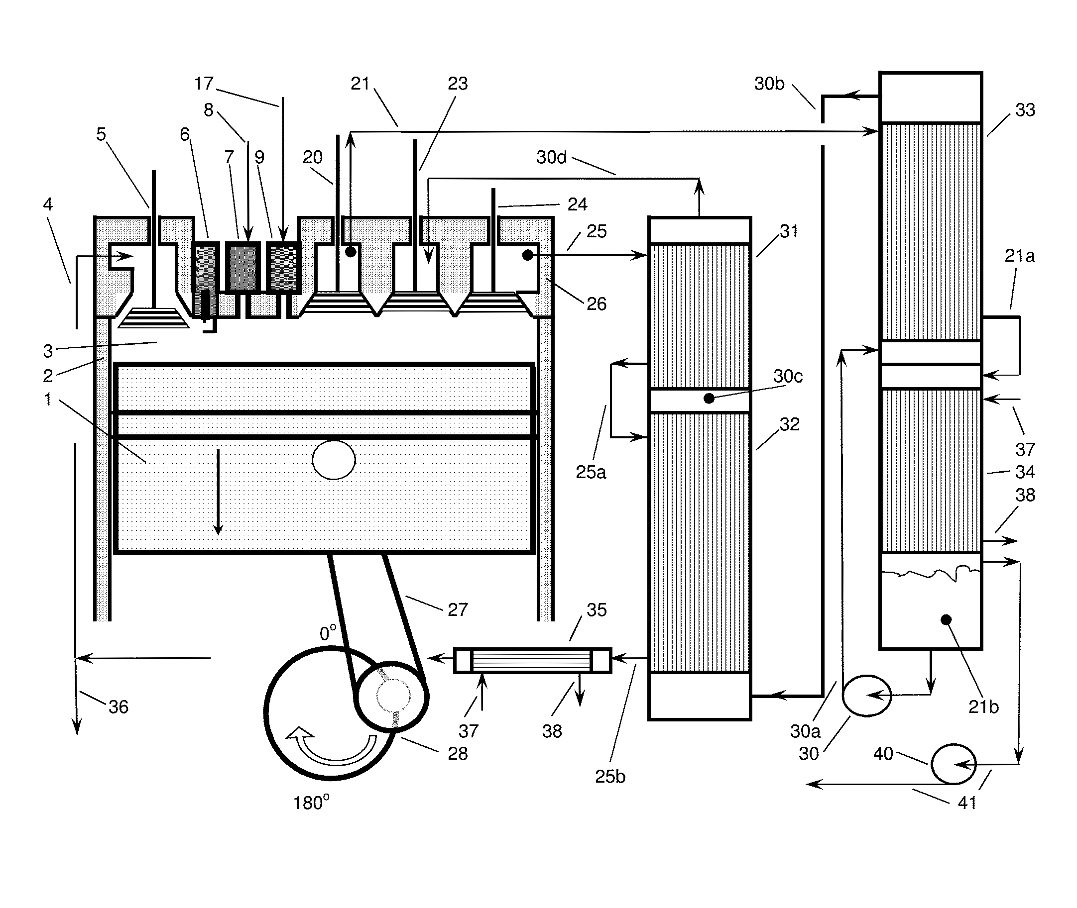
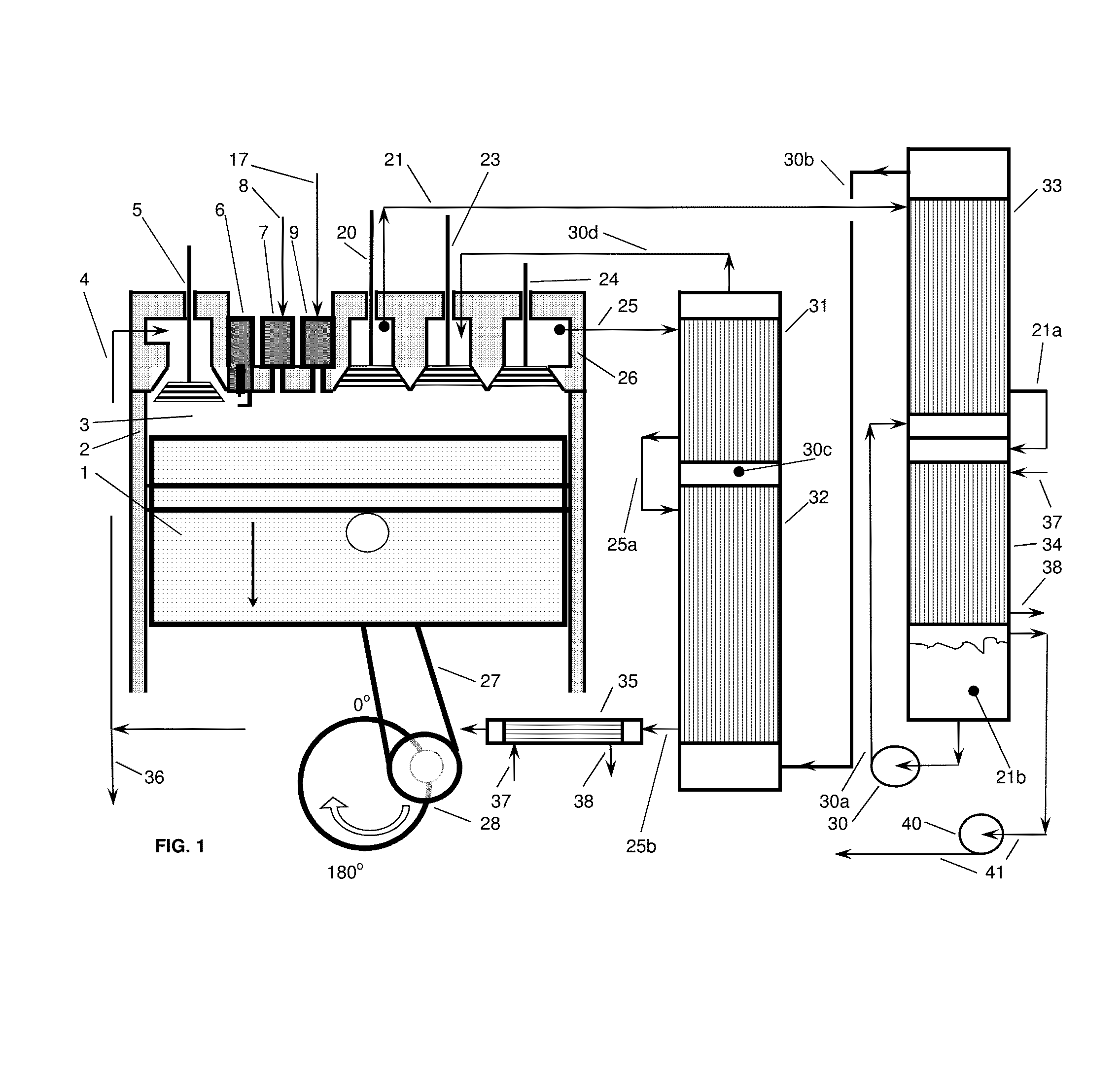
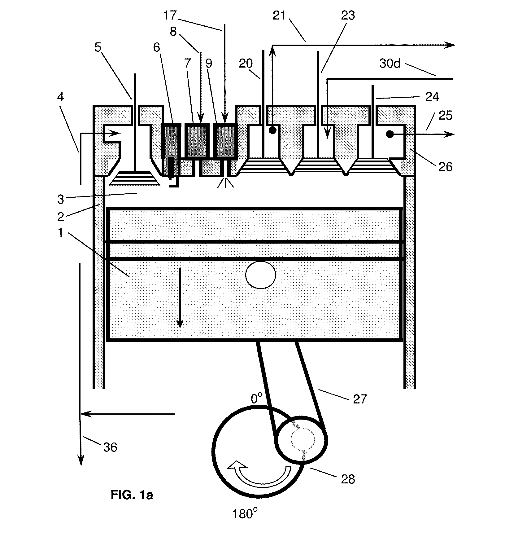
[0073]For simplicity in describing this invention, the figures illustrate only one piston inside one cylinder attached to one crankshaft. This invention may use any number of cylinders and pistons as well as multiple crankshafts. The figures are illustrative and are not drawn to scale but schematically depict this engine and the method of operating this engine. This engine may be either spark ignited (SI), compression ignited (CI), combination of SI and CI, or utilize some other means of igniting the combustible mixture. The fuels to be used in this engine include all hydrocarbons, coal dissolved in hydrocarbons with the ash removed, as well as hydrogen or mixtures thereof. It is understood that cylinder 2; cylinder head 26; connecting conduits 4, 17, 21, 21a, 25, 25a, 25b, 30a, 30b, 30c, and 30d; pump 30; and heat exchangers 31, 32, 33, 34 and 35 are all insulated to retain heat. This insulation will also absorb noise resulting in a quiet engine. This insulation is not shown for cl...


PUM


Abstract

A six stroke high thermal efficiency engine and a method for operating such an engine are disclosed. Oxygen or oxygen-enriched air is used as the oxidizer, heat is recovered from the two exhaust strokes, superheated steam is used in the second power stroke, and high levels of exhaust gas from stroke four are recirculated. Lean burn combustion is utilized to produce an oxygen rich exhaust which results in very low levels of particulates, unburned hydrocarbons, and carbon monoxide. Due to high thermal efficiency, carbon dioxide emissions are reduced per unit of power output. Use of oxygen or oxygen-enriched air as the oxidizer produces an exhaust containing very low levels of nitrogen oxides. The engine is insulated to conserve heat, resulting in reduced engine noise. An engine with high thermal efficiency, quiet operation, and low emissions is the result.

Description

CROSS-REFERENCE TO RELATED APPLICATIONS[0001]Not applicableFEDERALLY SPONSORED RESEARCH[0002]Not applicableSEQUENCE LISTING OF PROGRAM[0003]Not applicableBACKGROUND OF THE INVENTION[0004]1. Field of the Invention[0005]The present invention relates to reciprocating internal combustion engines in general, and more specifically, to engines equipped with heat recovery, heat recycle, and other heat conserving systems. The present invention also relates to a reciprocating internal combustion engine with reduced specific emissions of carbon dioxide, unburned hydrocarbons, carbon monoxide, and nitrogen oxides per unit of power produced.[0006]2. Description of Prior Art[0007]The internal combustion (IC) engine is well over 100 years old. The original US patent was issued to Nicolaus Otto on Aug. 14, 1877 for a four-stroke spark ignited (SI) engine. An earlier patent was issued to Otto for a four-stroke engine in Germany. A compression ignition (CI) engine, or Diesel engine, was invented a fe...

Claims


Application Information

Patent Timeline
IPC IPC(8): F02M25/03F02G5/02F02B75/02
CPCF02M25/03F02G5/02F02B75/02F02B47/02F02B75/021F02M25/10Y02T10/12
Inventor JUNG, PHILIP OWEN
Owner JUNG PHILIP OWEN
Learn More