High efficiency small molecule tandem photovoltaic devices

a photovoltaic device and small molecule technology, applied in the electrical field, can solve the problems of inability to exceed the product maximum total power generated by the pv device, difficult and expensive production, and difficult production of efficient crystalline-based devices, etc., to achieve the effect of minimizing spectral overlap, maximizing photocurrent, and economic production cos

Active Publication Date: 2016-09-01
RGT UNIV OF MICHIGAN
View PDF4 Cites 1 Cited by
  • Summary
  • Abstract
  • Description
  • Claims
  • Application Information

AI Technical Summary

Benefits of technology

[0024]Another object of the present invention is to provide a solar cell with an economical production cost.
[0025]It is a further object of the present invention to use relatively thick and strongly absorbing subcells with considerable

Problems solved by technology

However, efficient crystalline-based devices, especially of large surface area, are difficult and expensive to produce due to the problems inherent in producing large crystals without significant efficiency-degrading defects.
On the other hand, high efficiency amorphous silicon devices still suffer from problems with stability.
The maximum total power generated by a PV device is inherently incapable of exceeding the product, ISCVOC.
Such a process can be induced by the built-in electric field, but the efficiency at the electric fields typically found in organic devices (F˜106 V/cm) is low.
Single-junction small molecule OPVs have achieved a power conversion efficiency of >8%, but the narrow absorption range, low VOC,

Method used


Image

  • High efficiency small molecule tandem photovoltaic devices
  • High efficiency small molecule tandem photovoltaic devices
  • High efficiency small molecule tandem photovoltaic devices

Examples


example 2

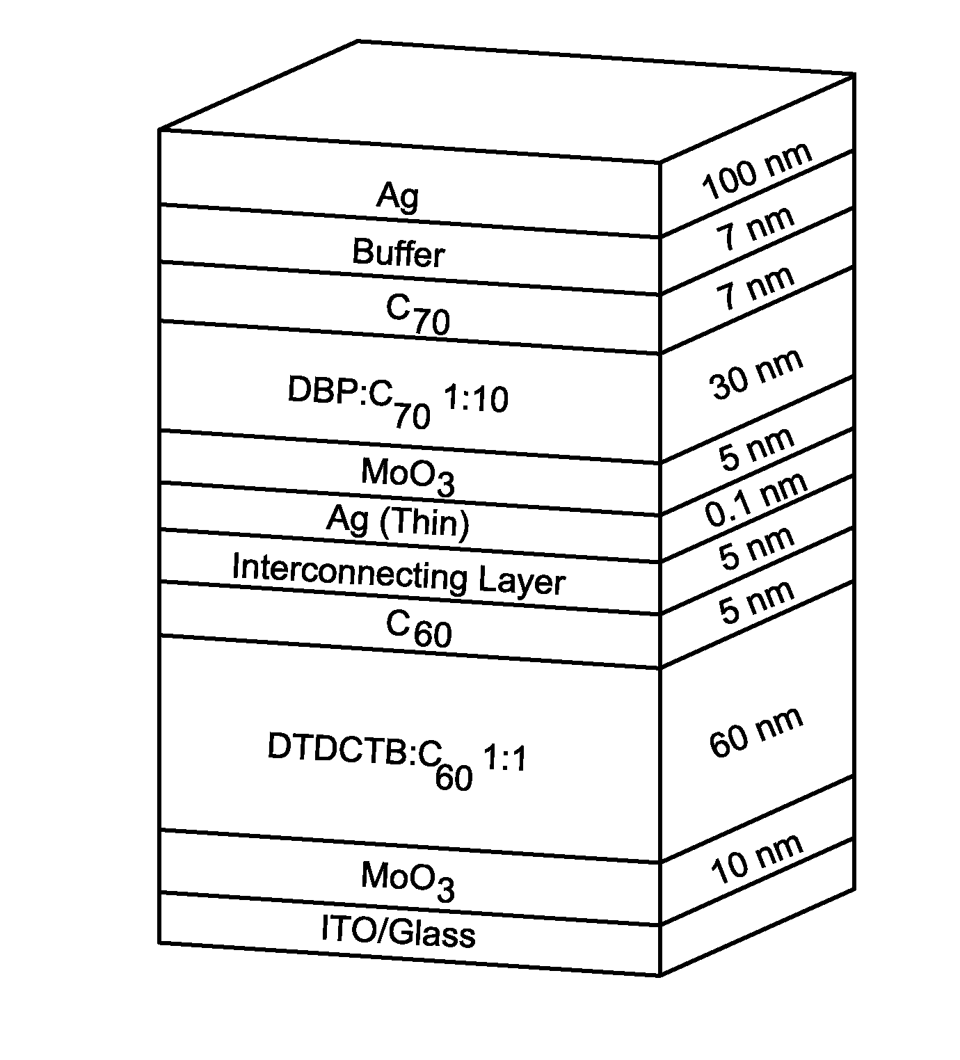
High Intensity with DTDCTB:C60 and DBP:C70 Subcells

[0098]It has been shown that optimized tandem structures employ subcells whose currents are approximately matched at the maximum power point (MPP) of operation. The power conversion efficiency penalty that is related to any mismatch in constituent subcell efficiencies is defined as:

Δη=1−(JMTVMT) / (JM1VM1+JM2VM2)

[0099]The optimal design corresponds to Δη=0. Here, JM and VM refer to the current density and voltage at the MPP. The subscript T refers to the tandem, and 1,2 refer to the two subcells. According to the simulated J-V characteristics of the subcells in FIG. 7B, the optimized tandem device in the previous example embodiment has Δη=0.6%. This is close to the ideal scenario where JMT=JM1=JM2 and MMT=VM1=VM2.

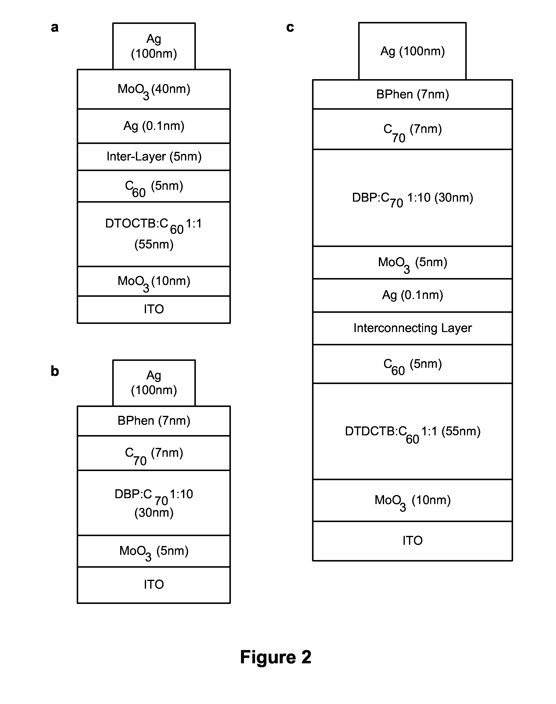
[0100]In one further tandem cell structure, the BPhen cathode buffer (7 nm, below the AG contact) was replaced with a high electron conductivity, exciton blocking compound BPhen:C60 (5 nm) / BPhen (2 nm) electron filter that re...

example 3

DTDCTB:C60 and DTDCPB:C70 Subcells

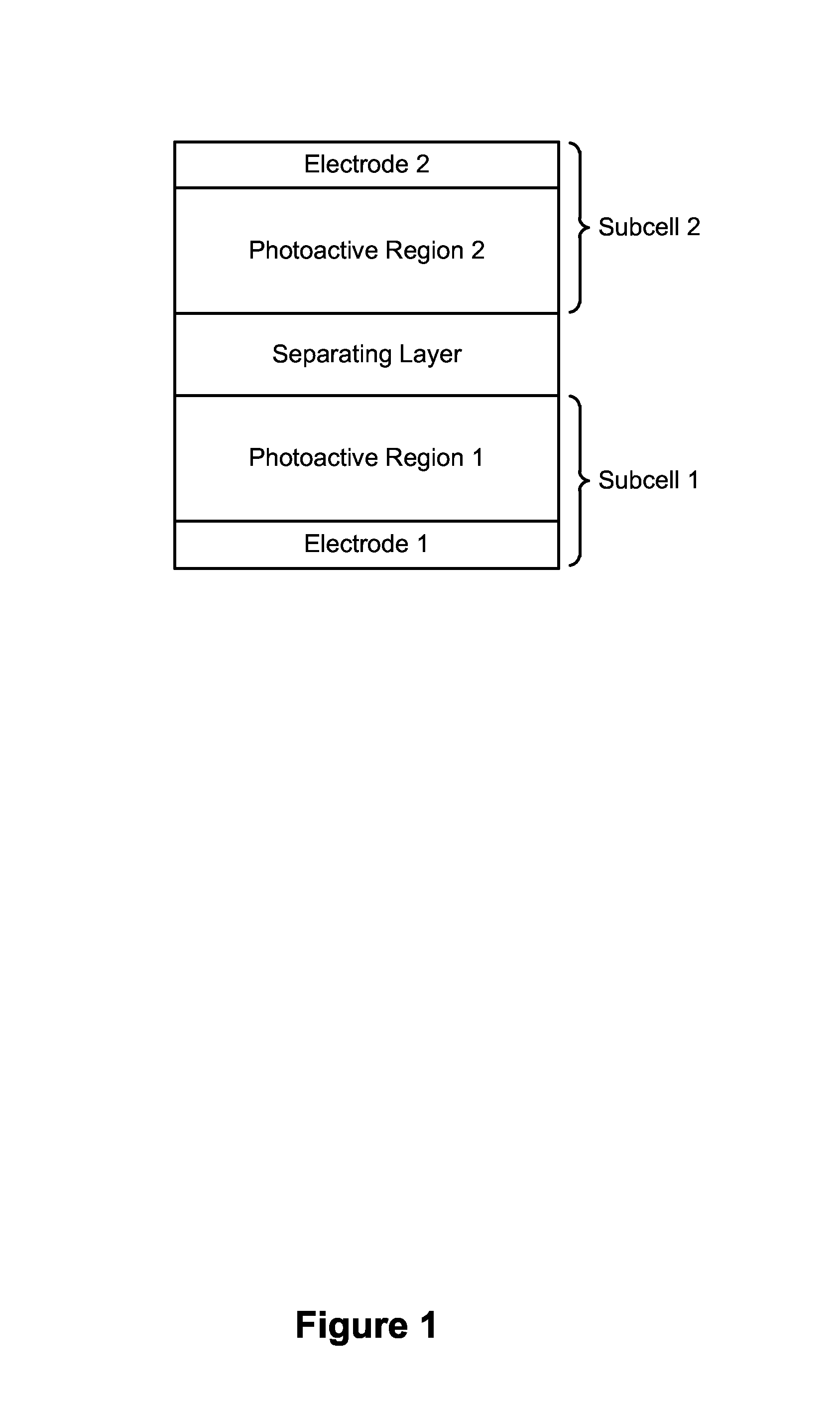
[0102]As further embodied herein, a small molecule tandem solar cell may be formed with a front subcell and a back subcell. The front subcell adjacent to the transparent anode may comprise the primarily orange-to-NIR absorbing donor, (DTDCTB) blended with C60 (DTDCTB:C60). The front subcell may be paired with a UV-to-yellow absorbing (2-[(7-{4-[N,N-Bis(4-methylphenyl)amino]phenyl}-2,1,3-benzothiadiazol-4-yl)methylene]propanedinitrile (DTDCPB) mixed with C70 (DTDCPB:C70) back subcell. The chemical structure of DTDCPB is shown in FIG. 10.

[0103]In the front subcell, the C60 intermolecular charge transfer (CT) absorption feature in the green is greatly reduced when diluted in DTDCTB, thus providing a spectrally complimentary system with the back sub-cell. The resulting tandem solar cell broadly covers the solar spectrum from λ=350 nm to 900 nm, achieving a simulated efficiency of 9.8% under standard illumination. The high efficiency again utilizes the p...


PUM


Abstract

A high efficiency small molecule tandem solar cell is disclosed. The tandem cell may include a first subcell comprising a first photoactive region and a second subcell comprising a second photoactive region. The first and second photoactive regions are designed to minimize spectral overlap and maximize photocurrent. The device may further include an interconnecting layer, disposed between the first subcell and the second subcell, that is at least substantially transparent.

Description

CROSS-REFERENCE TO RELATED APPLICATION[0001]This application claims the benefit of U.S. Provisional Application No. 61 / 895,837, filed Oct. 25, 2013, and U.S. Provisional Application No. 61 / 924,577, filed Jan. 7, 2014, both of which are incorporated herein by reference in their entirety.STATEMENT REGARDING FEDERALLY SPONSORED RESEARCH[0002]This invention was made with U.S. Government support under Contract Nos. DE-EE0005310 and DE-SC0000957 awarded by the U.S. Department of Energy. The government has certain rights in the invention.JOINT RESEARCH AGREEMENT[0003]The subject matter of the present disclosure was made by, on behalf of, and / or in connection with one or more of the following parties to a joint university-corporation research agreement: The Regents of the University of Michigan and NanoFlex Power Corporation. The agreement was in effect on and before the date the subject matter of the present disclosure was prepared, and was made as a result of activities undertaken within ...

Claims


Application Information

Patent Timeline
IPC IPC(8): H01L51/42H01L51/44
CPCH01L51/424H01L51/442H01L51/0061H01L51/0071H01L51/0047H01L51/0056H01L51/0046H01L51/0072H01L51/0068Y02E10/549H10K30/57H10K85/624H10K85/636H10K85/657H10K30/211H10K30/30H10K30/353H10K30/20H10K30/82H10K85/211H10K85/215H10K85/655H10K85/6572
Inventor FORREST, STEPHEN R.CHE, XIAOZHOUXIAO, XINZIMMERMAN, JERAMY
Owner RGT UNIV OF MICHIGAN
Why Eureka
Try Eureka