Medical device for embolic protection

a technology for medical devices and embolism, applied in the field of medical devices and procedures, can solve the problems of high morbidity and mortality, stroke, or even death, and avoid the risk of plaque dislodgement and iatrogenic embolization

Active Publication Date: 2016-09-15
PROTEMBIS
View PDF5 Cites 29 Cited by
  • Summary
  • Abstract
  • Description
  • Claims
  • Application Information

AI Technical Summary

Benefits of technology

[0033]In a preferred embodiment the method provides embolic protection for the brachiocephalic trunk and left common carotid artery. The preferred method comprises the step of introducing an embolic protection device into the patient's aorta, the embolic protection device comprising an expandable frame supporting a filter membrane. The frame comprises a frame loop to which preferably the filter membrane is connected partially of completely by surrounding a periphery of the frame loop. The frame loop is connected to the frame shaft. The frame loop is configured engaging an interior wall of the aorta to support the embolic protection device within the patient's aorta covering the ostia of the brachiocephalic trunk and left common carotid artery. In a compressed position the embolic protection device has a diameter which fits within the catheter for insertion into the patient's aorta. The method further comprises expanding the embolic protection device to its expanded state within the patient's aorta and allow blood to enter the side branch vessels to prevent embolic material from entering the side branch vessels, wherein the embolic protection device is recaptured into the catheter acquiring a compressed state within the catheter. Due to its method of use and site of placement of the device according to the invention, there is no necessity of entering with a guidewire or with the protection device within the carotid arteries, like for Claret Device patent US 2012 / 0172916A1, and with ValveNet™ device, avoiding the risk of plaque dislodgement and iatrogenic embolization to the brain.

Problems solved by technology

These diseases are a major cause of morbidity and mortality in the United States, Europe and throughout the world.
Periprocedural stroke constitute the most debilitating complication from the patient's perspective, associated with a high rate of morbidity and mortality.
During the performance of any endovascular or surgical procedure involving the passage of catheters across the aortic arch, air embolism, thrombus formation in the catheter or on its surface, or the dislodgement of plaque or other material by surgical or catheter manipulations can occur, and this debris can embolize into the carotid vessels resulting in neuropsychological deficits, stroke, or even death.
The main problems described with intravascular filtering devices include the placement of the filter in some segments within the carotid arteries with atherosclerotic plaques, the difficulty in its placement and retrieval, mainly during the recapture of the filter to withdraw the emboli from the body that can be difficult depending upon the volume of entrapped emboli, and the reduced perfusion through the filter due to the captured emboli, with the possibility of complete filling of the filter, obstructing the cerebral circulation during the procedure.
These procedures simultaneously place both carotid arteries at risk for emboli.
The chance of causing a stroke by selectively cannulating both carotid arteries, navigating a catheter within the artery and placement of a protective device is high, and the time and skill necessary to be exercised has also contributed to the lack of general application and use, despite of the high stroke risk during cardiac and aortic arch procedures.
Although this device is compatible with a low profile access port, its use is limited due to the fact that most of patients selected for transcatheter valve procedures are of advanced age and the incidence of severe tortuosity and calcification of the right subclavian artery is very high in these patients, preventing proper navigation and delivery of the device in the artery at the desired position.
Although this device is compatible with variable arch anatomies and it does not use a filter recovery step, it has certain disadvantages such as the need of a 7 French access port which is too large for being used by the radial artery in the majority of patients.
Furthermore, both devices exhibit the same and more important disadvantage: the need to selectively cannulate both carotid arteries with a guide wire extending between the brachiocephalic artery to the right and left carotid arteries, crossing the aortic arch, bringing unavoidably intravascular handling.
The use of a guide wire arranged extending between the aortic arch and the brachiocephalic artery leads to unfavorable intravascular handling.
Thus a risk for iatrogenic caused embolization to the right carotid artery or damage to the vessel wall is present.
Furthermore, there is no fixing mechanism or support mechanism that holds the device in place during the procedure, so that with the constant aortic blood flow and the passage of catheters through the aortic arch, the device can be hooked or displaced.
Potential problems of this device include the necessity to use a big size access port and introductory sheath, making its use nearly impossible percutaneously through the radial artery.
Moreover, as its design includes the pass of blood flow only through the perfusion lumen; this could be substantially hindered through the aortic arch, thus causing possible periods of cerebral hypoperfusion during the procedure.
The most important drawbacks of this device are that using a big size access port and introductory sheath, restricts its use strictly to the femoral approach, which in turn is occupied by the large catheters of the endovascular procedures, increasing the risk of vascular complications at the femoral access site.
Moreover, the device may be difficult to extract from the aortic arch, as a stent like design is devised for permanent implantation and removing a stent may harm the implantation site.
Limitations of this device include its applicability mostly to open heart surgery and in some cases of cardiac procedures by direct aortic approach, excluding its use in the vast majority of endovascular procedures requiring cerebral embolic protection.
Also, it's not easy to use, the device most be secured to the lumen of the aorta through some mechanism including sutures, surgical clips, hooks, adhesive materials, substantially rigid sleeves, or frictional engagement, making difficult to accomplish by transvascular access.
Because the device completely spans the aorta, the passage of catheters and wires coming from others vascular accesses through the aortic arch is not possible.
Therefore, the device can damage the vessel walls or can get hooked with catheters or wires during its passage into the aortic arch.
Also, the device has a stabilizer into the brachiocephalic trunk that can damage the vessel wall.
Moreover, due to its design and the need of 9 French sheaths, its introduction by the radial artery and the passage of catheters and wires coming from other arterial vascular accesses besides the femoral artery is not possible.
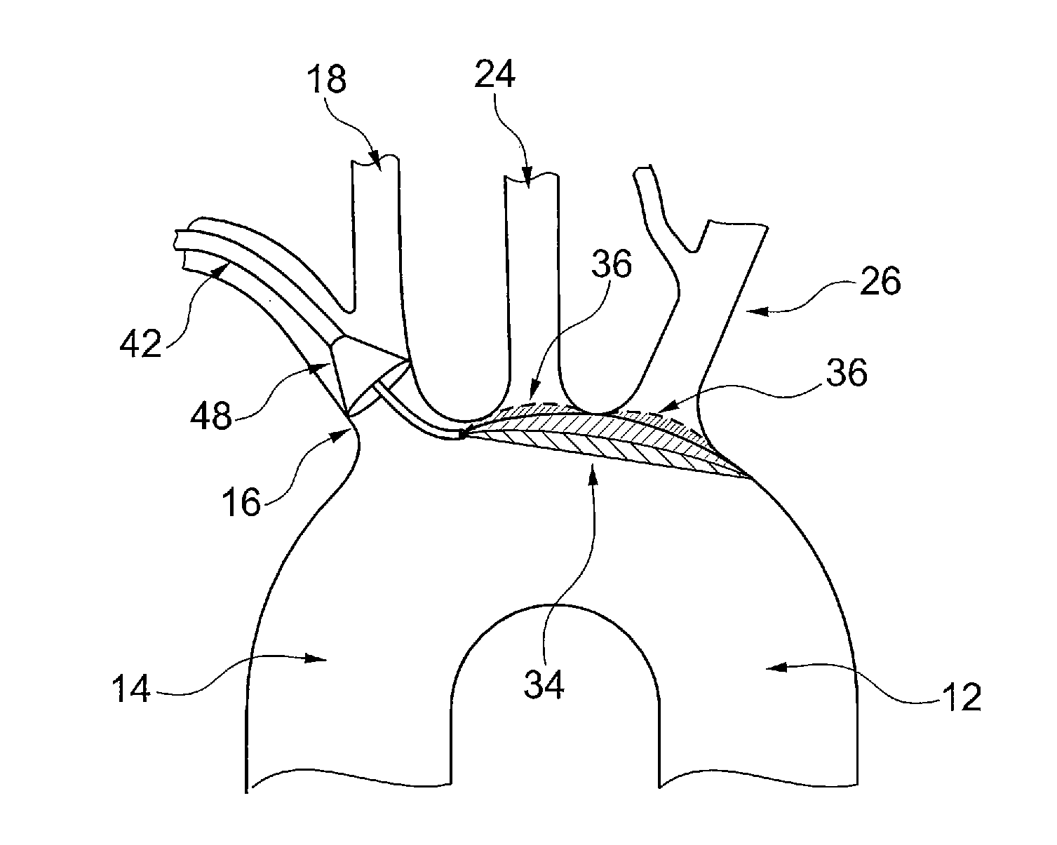
The known device leaves a space between the mesh, the ostia of the side branch vessels and the lateral walls of the aortic arch, causing incomplete sealing and protection of the ostia of the side branch vessels, and allowing the passage of microembolic particles to the brain.
Furthermore, the supporting member can damage the aortic arch wall during deployment and positioning of the protective device, or by an unintentional movement or shove by the catheters passing through the aortic arch during the procedure.
Also, the device will have to be very large in order to cover the ostia of the three side branch vessels of the aortic arch, making it voluminous, not easy to handle within the aortic arch, and unlikely to have a low profile in order to use the radial artery as vascular access route.

Method used


Image

  • Medical device for embolic protection
  • Medical device for embolic protection
  • Medical device for embolic protection

Examples


Embodiment Construction

[0049]FIG. 1 shows in a schematic drawing of the aortic arch 10 with its descending aorta 12 and ascending aorta 14. The ascending aorta 14 leads directly to the aortic valves and the heart. In the aortic arch 10 there is the brachiocephalic trunk 16 from which the right common carotid artery 18 and the right vertebral artery 20 and the right subclavian artery 22 branches off. Next in the aortic arch is the left common carotid artery 24 which is followed by the left subclavian artery 26. The left vertebral artery 28 branches off from the left subclavian artery 26.

[0050]FIG. 2a shows an embolic protection device 30 in its expanded state. The embolic protection device 30 has an elongated frame shaft 32, which is flexible to be bent. Furthermore, the embolic protection device comprises a closed frame loop 34. The frame loop 34 carries the filter membrane 36. Between the frame shaft 32 and the frame loop 34 there is the connection point 38. The connection point 38 may have a triangular ...


PUM


Abstract

Medical device for embolic protection in an aortic arch, comprising a catheter having a shaft and a distal end portion of the shaft, an expandable embolic protection device having a filter membrane and a frame. The frame comprises a frame loop and an elongated frame shaft having a distal end portion connected to the frame loop in a connection point, in its expanded state the frame loop spans said filter membrane and bending means to bend the distal end portion of the catheter and/or the distal end portion of the frame shaft. The medical device comprises a protective state in which the distal end portion of the catheter is bent, the embolic protection device is expanded, the frame shaft extends in a longitudinal direction of the bent distal end portion and the expanded frame loop being completely positioned distally of the connection point.

Description

CROSS-REFERENCE TO RELATED APPLICATIONS[0001]This application is a 371 National Stage application of International Application No. PCT / EP2014 / 071944 filed on Oct. 14, 2014, which claims priority of European Patent (EP) application Serial Number 13188522.0 filed on Oct. 14, 2013, both of which are incorporated herein by reference in their entireties.BACKGROUND OF THE INVENTION[0002]1. Field of the Invention[0003]The invention pertains in general to the field of medical devices and procedures for applying such medical devices. Most particularly, the present invention relates to a device and a method for providing embolic protection to a patient's aortic arch vessels by diverting and / or capturing solid particles during cardiac surgery and interventional cardiology procedures.[0004]2. Description of the Prior Art[0005]Atherosclerosis and thromboembolic disorders, such as stroke, pulmonary embolism, peripheral thrombosis, and the like, affect a large amount of population. These diseases ...

Claims


Application Information

Patent Timeline
Patent Type & Authority Applications(United States)
IPC IPC(8): A61F2/01
CPCA61F2/013A61F2250/0059A61F2002/011A61F2002/016A61F2230/0008A61F2230/0069A61F2230/0093A61F2250/0036A61F2/01A61F2/011A61F2/82A61F2/86
Inventor VON MANGOLDT, KARLRASMUS, CONRADJIMENEZ DIAZ, VICTOR ALFONSODIAZ LOPEZ, CARLOS MARIA
Owner PROTEMBIS
Why Eureka
Try Eureka