Despite an increased focus on this issue, many subsequent reports, including the
World Health Organization's “2014 Update on the Progress of Drinking Water and
Sanitation”, describe the uneven and unequal progress being made towards achieving
fresh water supply goals.
The hazards posed by an insufficiency and / or incontinuity in the supply of
clean water are particularly acute.
Further still, the supply of
fresh water is often seasonally inconsistent.
Global warming, and any climate changes brought about, may further threaten these regions.
Understandably, an insufficient and / or intermittent supply of fresh water may lead to a variety of crises, including famine,
disease, death, forced
mass migration, cross-region conflict / war, and collapsed ecosystems.
Adding to global shortages of fresh water is the fact that the distribution of freshwater that is easily available is vastly unequal.
As naturally occurring fresh water is typically confined to regional drainage basins, transport of fresh water to urban localities must be undertaken with ever-increasing costs.
The
resultant fresh water shortages necessitate methods of obtaining fresh water from non-fresh water sources such as, but not limited to,
seawater,
brackish water and / or even waste water.
Both the fracturing chemicals and fresh water that is injected into the well during the fracturing process tend to dissolve salts in the rock formation, thus increasing the
salinity of the flowback water.
Although there are many existing processes for producing fresh water from
seawater brackish water, and / or waste water, the majority of them require massive amounts of energy.
For example, despite being the current leading
desalination technology,
reverse osmosis (RO) is energy intensive and still relatively inefficient due to the
high pressure required to drive water through membranes and their tendency to foul.
In large-scale plants, the specific
electricity required can be as low as 4 kWh / m3 at 30%
recovery, as compared to the theoretical minimum of around 1 kWh / m3; while smaller-scale RO systems (e.g., aboard ships) are even less efficient.
As such, when these technologies are employed, they are usually done on a large scale and are mainly suitable for those economically advanced and resource-rich regions of the world, as many developing countries lack sufficient
energy resources to carry out these methods.
These types of humidification devices have a low effectiveness due to their low water hold up.
Moreover, the pressure drop in the water stream is high due to the losses in the spray nozzels.
As for wetted-wall towers, these devices suffer from a low
water flow rate capacity since the water only flows on the inner surface of the
tower, and they are not preferred.
However, in some operations, the fluid passing through the
packed bed may contain suspended
solid particles that can accumulate on the packing material and cause a reduction in the gas-liquid volumetric flow rates and, in extreme cases, a plugging of the
tower.
This results in the formation of bubbles in the
pool, or bath of accumulated hot water.
It is noted that the smaller the porous openings, the greater risk of
fouling of the openings by sediments, salts and other contaminants found in a feed liquid.
Porous structures having too great of a total porous surface area often suffer from
cracking, or breaking, with increased
gas pressure stresses.
The effect of such an arrangement is that the air streams or bubbles that form are continuously distorted and become subject to turbulence which is created as they pass through the much denser thermal layer or
layers of the liquid bath.
Any impediments to the bubble formation process will directly
impact the level of foam formation.
However, although the presence of foam increases the rate of mass and
heat transfer, the
overall efficiency of the bubble column humidifier will decrease if the foam (bubbles) are allowed to return to a preceding, or prior, chamber.
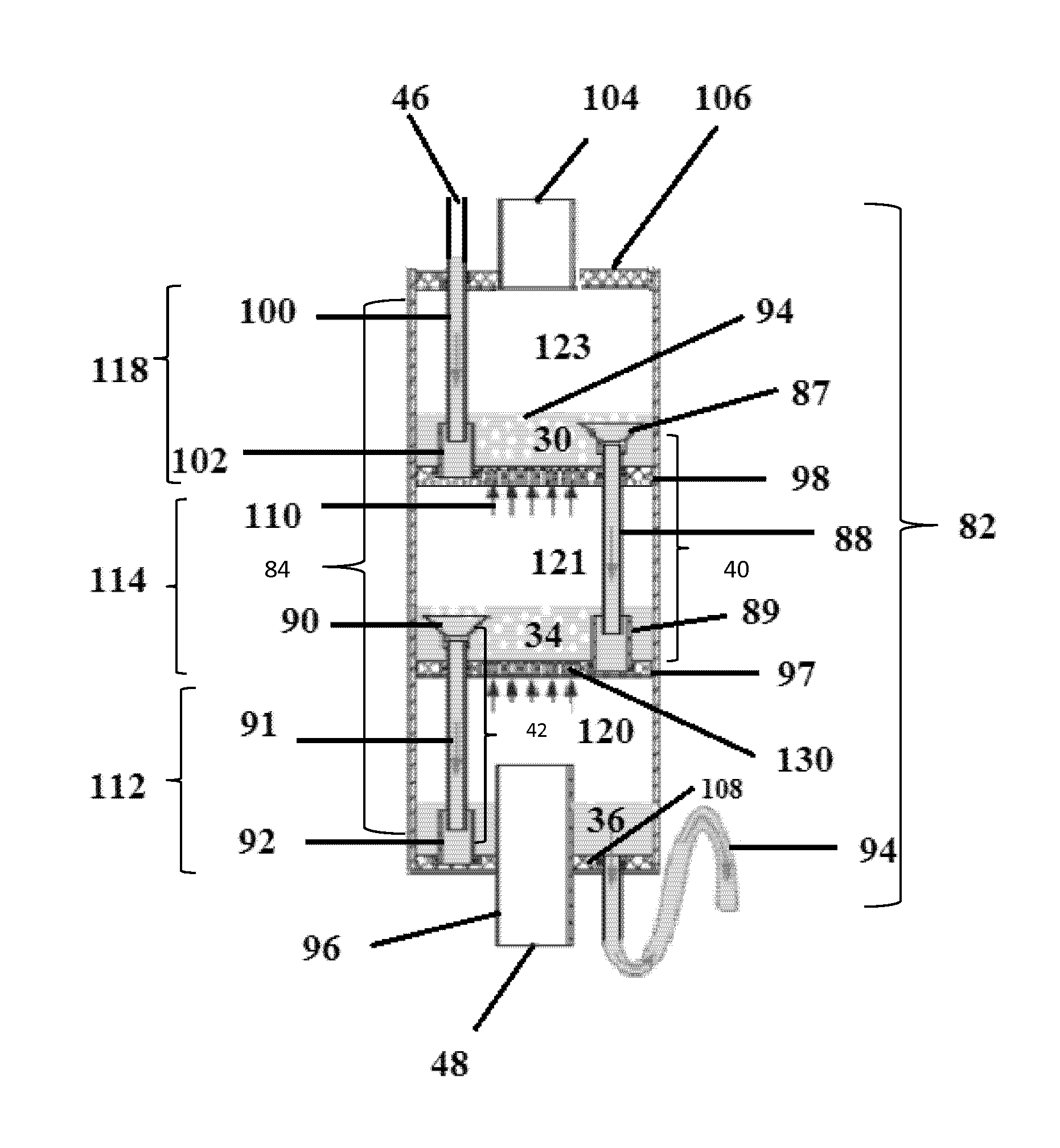
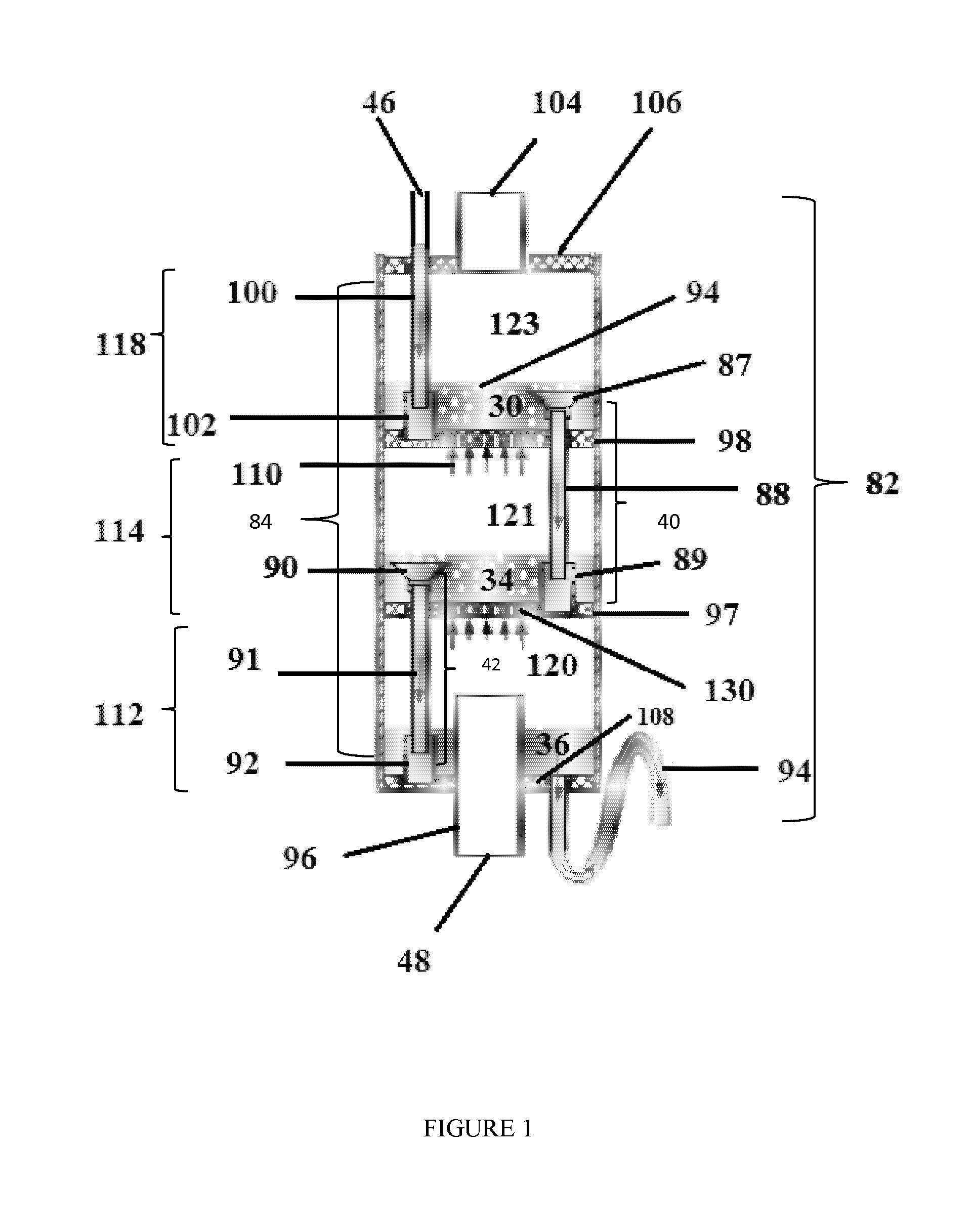
In previous apparatus, high levels of foam resulted in the
direct entry of bubbles into downcomer units so as to be transported to adjacent underlying chambers, thus reducing efficiency.
Furthermore, if a high level of foam contacts the porous plate of the adjacent overlying chamber, this may result in a
bursting of the bubbles and release of the vaporizable component, thus also reducing efficiency.
If the downcomer unit is contiguous with the exterior shell of the bubble column humidifier, the watergate, or any part of the downcomer, may not be easily adjusted nor replaced in case of breakage.
Truncated water gate designs have several inherent limitations.
For example, the water gate may not provide a sufficient length so as to cause the fluid in the chamber below to back up into the water gate.
This will impede the flow of the liquid, and may even cause it to re-enter the chamber from which it originated.
Also, any water gate releasing its contents at a location above the water bath increases the probability of sediments from the liquid, such as salts from
seawater, accumulating on the porous structure.
This may foul the openings of the porous structure, such as a sparger, so as to impede the flow of a gas, such as air, and reduce the efficiency of the apparatus.
This method increases the
heat transfer rates in the condenser at the expense of energy efficiency, as the energy from the humid air entering the dehumidifier is not directly recovered to preheat the seawater.
Thus, although the cost of the dehumidification device is reduced, the energy costs associated with this method actually increase.
However, some bubbles may leave with the water stream; subsequently reducing the heat
recovery in the humidification process.
However, in these two references, it is not possible to adjust the height of
water level, and, most significantly, numerous bubbles may leave with the water stream.

