
Multilayer ceramic capacitor

a multi-layer ceramic capacitor and ceramic capacitor technology, applied in the direction of fixed capacitors, stacked capacitors, fixed capacitor details, etc., can solve the problems of crack generation, reduce reduce etc., and achieve the effect of reducing the effective area of internal electrode layers and reducing the capacitance of multi-layer ceramic capacitors

Inactive Publication Date: 2016-10-06
TAIYO YUDEN KK
View PDF13 Cites 63 Cited by
  • Summary
  • Abstract
  • Description
  • Claims
  • Application Information

AI Technical Summary

Benefits of technology

The present invention provides a large-capacitance multilayer ceramic capacitor with excellent thermal shock resistance and sufficient suppression of cracks. The technical effects achieved by limiting the faces on which the external electrode is formed and maintaining a specific relationship between the thickness of the external electrode and thickness of the cover layer are a limitation of stress generating as a result of thermal expansion of the external electrode and an increase in the number of internal electrode layers to be stacked. The thinness of the cover layer allows for an increase in the number of internal electrode layers to be stacked and improvements in moisture resistance reliability of the capacitor.

Problems solved by technology

The constitutions disclosed in Patent Literatures 1 and 2 have void parts provided in the internal electrode layers, but presence of such voids reduces the effective area of internal electrode layers and thereby reduces the capacitance of the multilayer ceramic capacitor.
However, reducing the thickness of the cover layer causes the thermal shock resistance of the multilayer ceramic capacitor to drop and makes it easy for cracks to generate in the cover layer, particularly where the external electrode is wrapped around the principal face, and it became clear that such a problem of cracks cannot be solved by the constitutions proposed in Patent Literatures 1 and 2.

Method used


Image

  • Multilayer ceramic capacitor
  • Multilayer ceramic capacitor
  • Multilayer ceramic capacitor

Examples


examples

[0109]The present invention is explained in greater detail below using examples. It should be noted, however, that the present invention is not limited to these examples in any way.

[0110]Manufacturing of Multilayer Ceramic Capacitor

[0111]Dy and Mg were each added by 1.0 mol, and V and Mn were each added by 0.5 mol, per 100 mol of barium titanate of 0.1 μm in average grain size, into which organic solvent whose primary constituent is alcohol, polyvinyl butyral resin, dispersant, and plasticizer were mixed and dispersed to produce a coating slurry. Then, this slurry was coated on a base material using a die-coater to produce a dielectric green sheet. The amount of slurry supplied to the die-coater was adjusted to control the thickness of the sheet.

[0112]Next, the aforementioned dielectric green sheet was screen-printed with a conductive paste prepared by mixing and dispersing Ni powder of 200 nm in average grain size, organic solvent whose primary constituent is alcohol, ethyl cellulo...


PUM

PropertyMeasurementUnit
Thicknessaaaaaaaaaa
Thicknessaaaaaaaaaa
Thicknessaaaaaaaaaa

Abstract

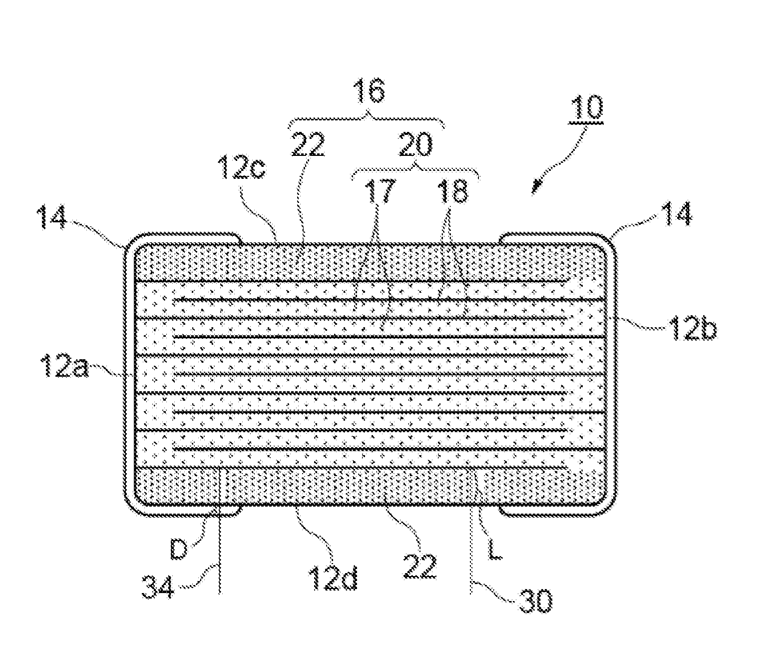
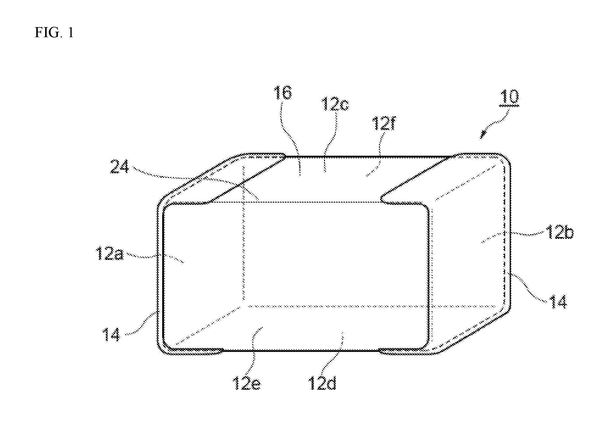
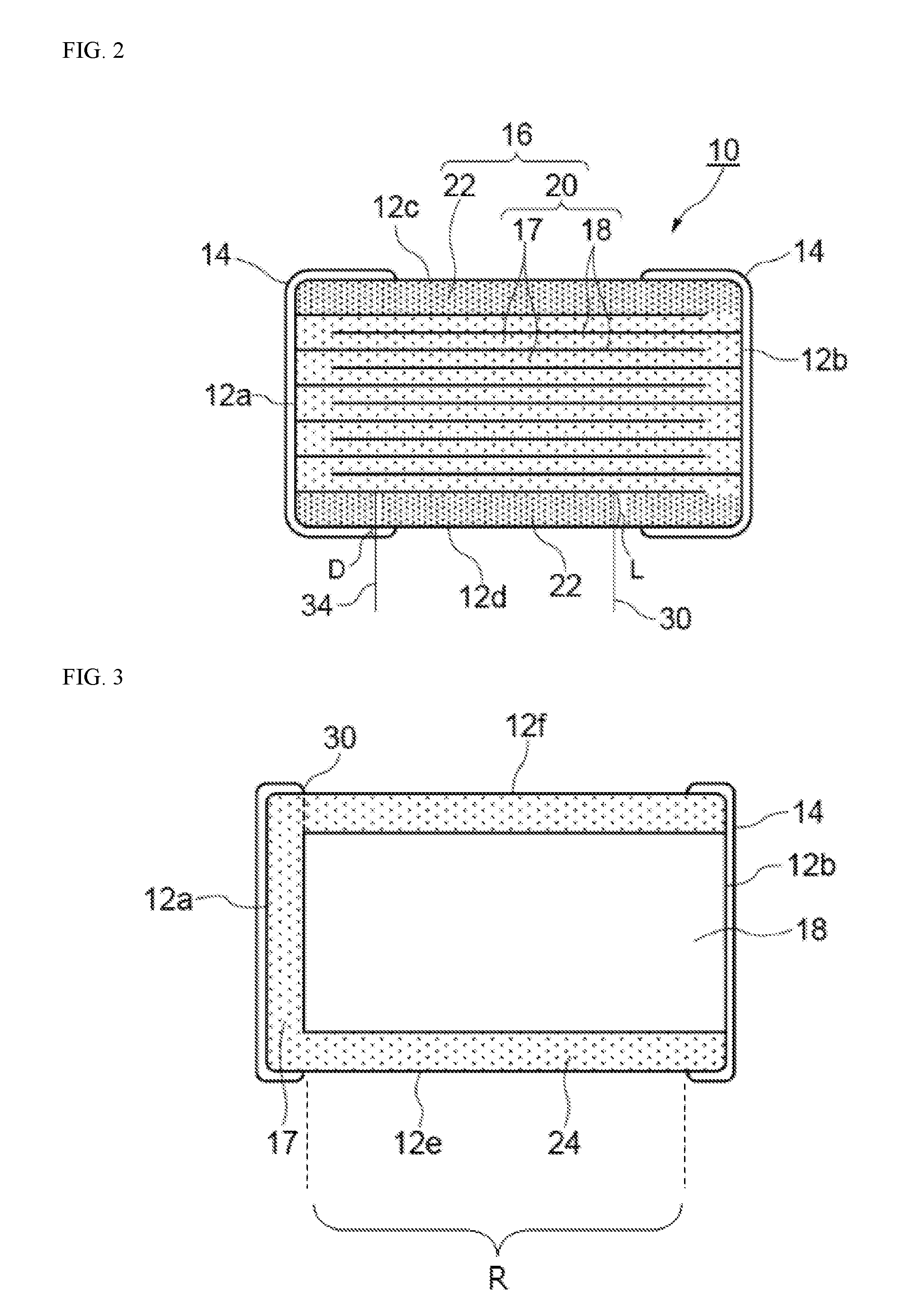
A multilayer ceramic capacitor includes an element body of roughly rectangular solid shape which is constituted by dielectric layers alternately stacked with internal electrode layers having different polarities, with a pair of cover layers formed on it to cover the top and bottom faces in the direction of lamination of the foregoing, and which has a pair of principal faces, a pair of end faces, and a pair of side faces, wherein external electrodes are formed on the pair of end faces and at least one of the pair of principal faces of the element body, and Tt representing the thickness of the external electrode and Tc representing the thickness of the cover layer satisfy the relationship of Tt≦Tc. The multilayer ceramic capacitor has large capacitance and also exhibits excellent thermal shock resistance while sufficiently suppressing generation of cracks.

Description

BACKGROUND[0001]1. Field of the Invention[0002]The present invention relates to a multilayer ceramic capacitor exhibiting excellent thermal shock resistance.[0003]2. Description of the Related Art[0004]In recent years, the high demand for smaller electronic components to support higher-density electronic circuits used in mobile phones, tablet terminals, and other digital electronic devices is accelerating the development of smaller, larger-capacitance multilayer ceramic capacitors (MLCC) which constitute these circuits.[0005]The capacitance of a multilayer ceramic capacitor is directly proportional to the dielectric constant of the material constituting the dielectric layers that in turn constitute the capacitor, the number of dielectric layers, and the effective internal electrode layer area or specifically the area of the overlapping parts of the internal electrode layers led out to the external electrodes alternately, and is inversely proportional to the thickness of one dielectr...

Claims


Application Information

Patent Timeline
IPC IPC(8): H01G4/248H01G4/232H01G4/30
CPCH01G4/248H01G4/232H01G4/30H01G4/12
Inventor KITAMURA, SHOHEIKONISHI, YUKIHIROMIZUNO, KOTAROKATO, YOICHIKOWASE, YUSUKEMAKINO, TORUTANAKA, YOSHINORI
Owner TAIYO YUDEN KK
Learn More