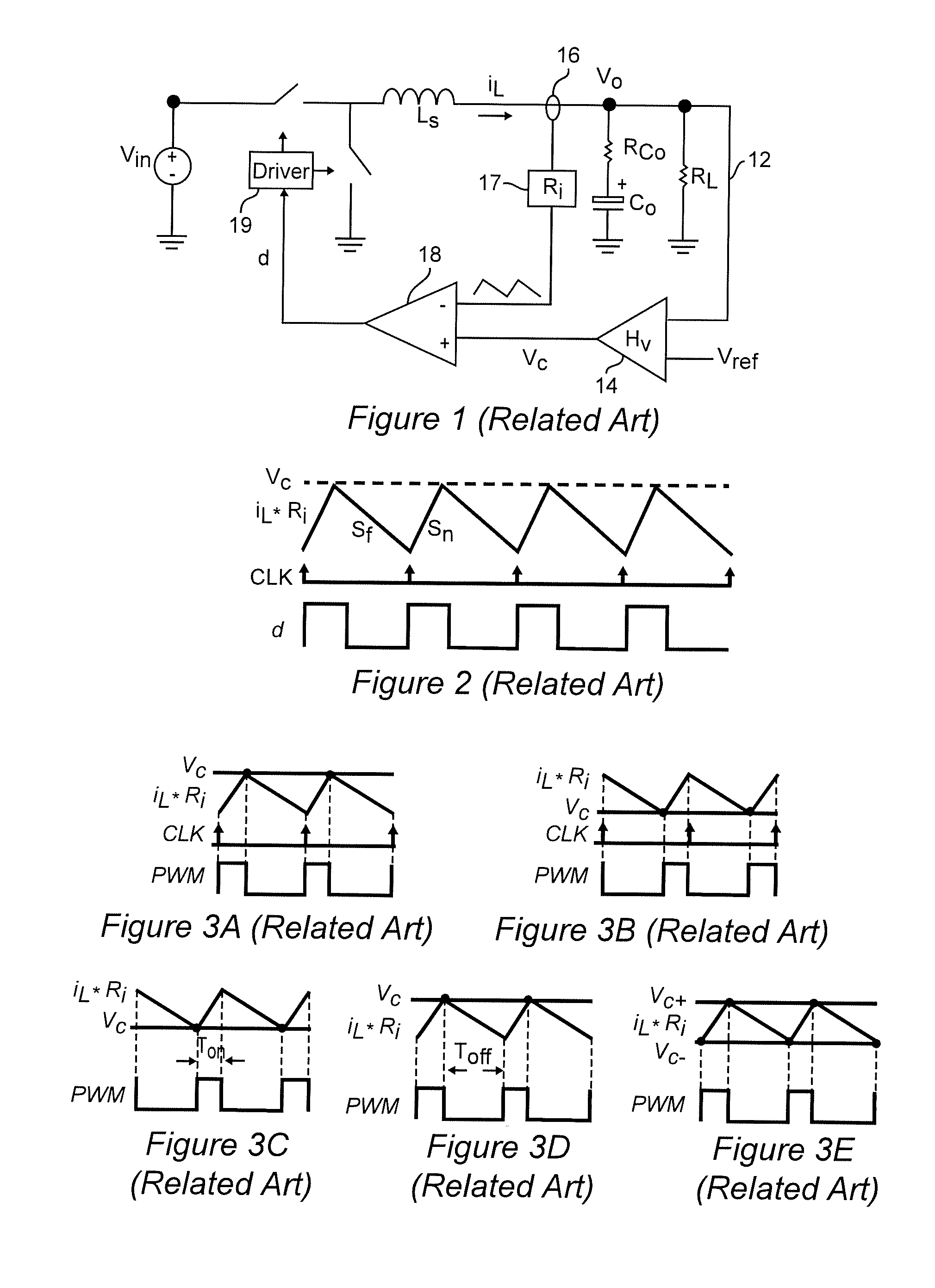
Therefore, constant on-time (COT) and constant off-time arrangements are generally preferred but also have significant limitations.
One significant drawback of COT control is the variation of
switching frequency, fsw, over the full range of switching
duty cycle when the load is variable over a wide range.
Accordingly the excess charge delivered to the output /
filter capacitor causes a degree of overshoot in the output voltage.
However, the regulation tolerance and signal
propagation time may cause the switching pulse to be extended beyond the required time causing over-correction and ring-back as illustrated within the dashed line in FIG. 10.
However, this latter approach, while improving load
transient response time and reducing undershoot is only effective to eliminate undershoot for one particular magnitude of load current change.
The drawback is that if the load transient is relatively small but still sufficient for loss of
voltage regulation (or the load transient detection arrangement subject to
false detection due to
noise or the like), producing only a small undershoot, excess charge may be delivered to the
filter capacitor and cause ring-back as shown in FIG. 13 as contrasted with the case where the
Ton only causes undershoot that is tolerable.
In this regard, it is also difficult to determine a threshold for load transient detection that will be appropriate for all values of load amplitude and
slew rate.
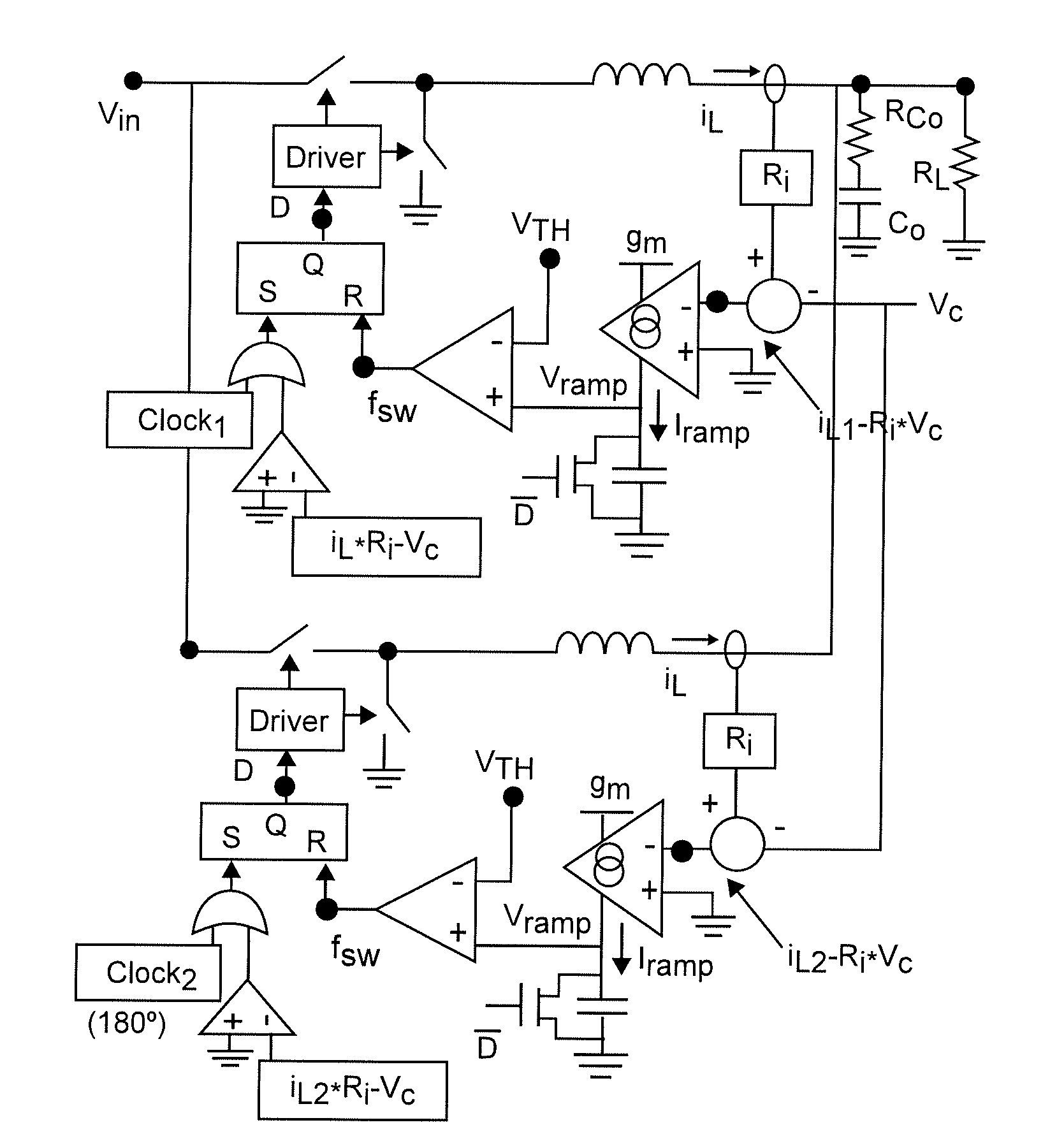
However, because individual pulse of a
single pulse train (based on a sum of the currents of the individual phases are distributed in a commutating manner, they cannot overlap to provide improved load
transient response as shown in the key waveforms of FIG. 15.
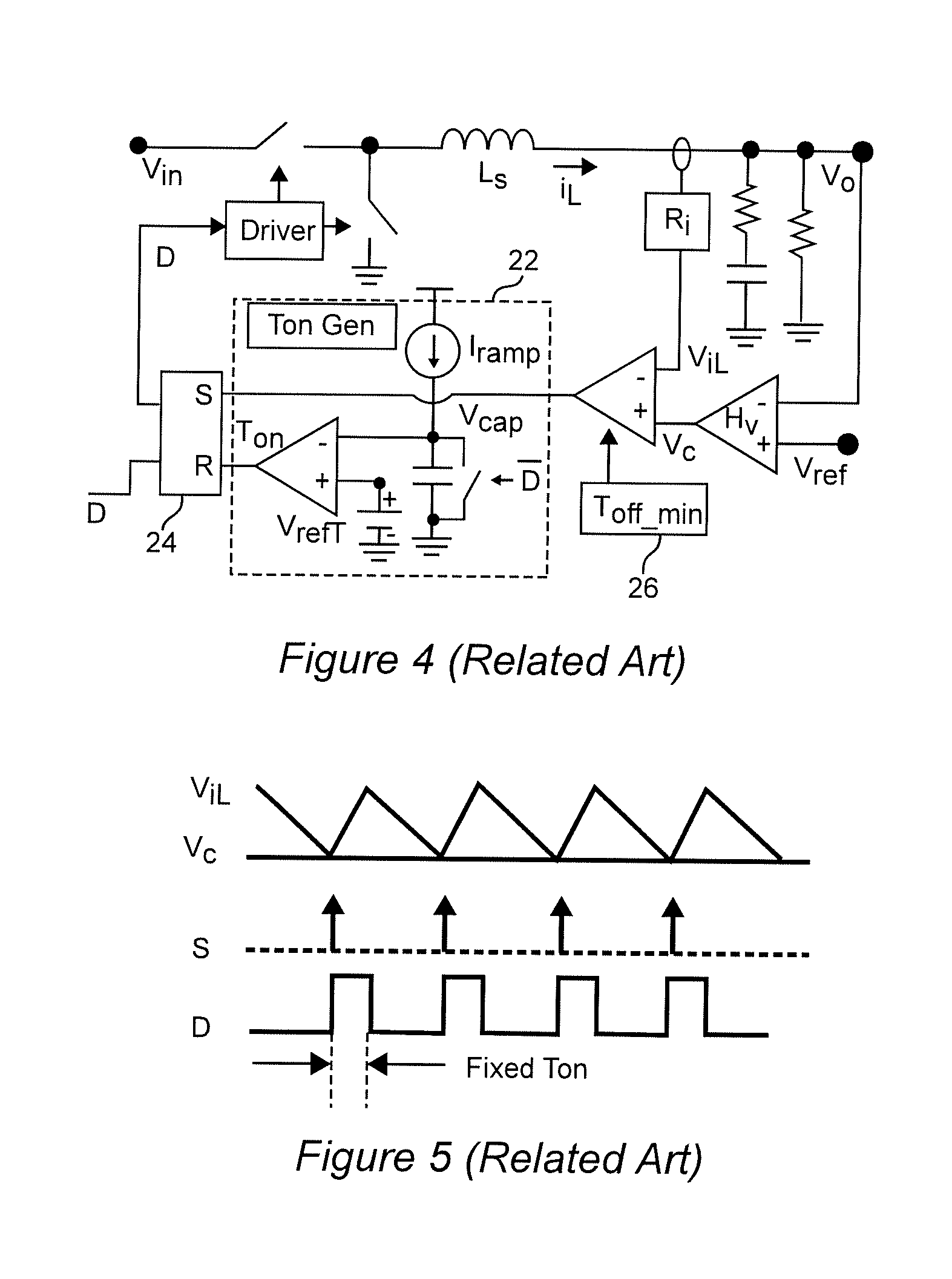
A significant issue in multi-phase power
converters, particularly power converters operating at a
fixed frequency or using adaptive on-time (AOT) control such that the
duty cycle of the switching pulse
train can vary, is that of
ripple cancellation and the
noise susceptibility engendered thereby.
Unacceptable performance will therefore result during periods of total
ripple cancellation even though such periods may be brief.
However, use of such an external ramp waveform causes peaking of
output impedance and overshoot to appear as illustrated graphically in the small signal characteristics shown in FIG. 19 as the external ramp overwhelms the
small amplitude of isum*Ri near the
inductor current
ripple cancellation points which, in turn, require an increase in output
capacitance to reduce overshoot.
As is particularly evident in FIG. 19, with increase of slope of the external ramp, Se, the
high frequency pole approaches the
low frequency pole and compromises the phase of the
loop gain while the
output impedance of the converter increases which, in turn, increases undershoot and overshoot.
Additionally, as shown graphically in FIG. 20, the load transient response can be slowed by the application of an external ramp since the external ramp makes the overlapping of different phases more difficult.
While this approach is generally effective, complexity increases greatly with increased numbers of phases due to the requirement of a synchronized and
phase shifted clock and a PLL for each phase.
Further, stability problems may be caused by the bandwidth of Tp and the trade-off with
system performance in regard to transient
response time.
However, for large step-up load transients, several switching cycles may be required to again reach
steady state operation and, in such a case, the load transient response will occur in steps and be less than optimally rapid and a degree of undershoot will occur.
Therefore the disadvantages of poor small signal property due to the double pole at half the
switching frequency and the quality factor (Q) is a function of the load (unlike the
peak current mode control discussed above) and the difficulty of achieving stability over a large load range is of less consequence and tolerable for some applications.

