MEMS silicone microphone and manufacturing method thereof

a silicone microphone and manufacturing method technology, applied in the field of silicone microphones, can solve the problems of ineffective methods, significant affecting the diaphragm sensitivity, and changing capacitors, and achieve the effects of improving sensitivity, reliability and yield, and simplifying manufacturing processes

Active Publication Date: 2016-10-20
MICROLINK SENSTECH SHANGHAI LTD
View PDF1 Cites 21 Cited by
  • Summary
  • Abstract
  • Description
  • Claims
  • Application Information

AI Technical Summary

Benefits of technology

[0010]One object of this invention is to overcome the drawbacks in the prior arts and provide a method to fabricate MEMS silicon microphones with simplified manufacturing processes, improved sensitivity, reliability and yield.

Problems solved by technology

Once the highly sensitive diaphragm senses the external acoustic pressure, the gap between diaphragm and backplate will change, thereby resulting in a capacitance change.
Based on the prior art, the fabrication of diaphragm suffers hardly controllable residual stress, significantly affecting the diaphragm sensitivity.
Unfortunately, all these two methods are not effective and complicated with limited reproducibility; third, the change of diaphragm structure, such as corrugated or floating diaphragm, or the introduction of some small grooves on the diaphragm can also reduce the residual stress and improve sensitivity.
However, this kind of methods will result in process complication, cost increase and yield reduction.

Method used


Image

  • MEMS silicone microphone and manufacturing method thereof
  • MEMS silicone microphone and manufacturing method thereof
  • MEMS silicone microphone and manufacturing method thereof

Examples


Embodiment Construction

[0048]Exemplary embodiments will herein be described in detail with the understanding that the present disclosure is to be considered as an exemplification of the principles of the present invention and is not intended to limit the broad aspect of the invention to the embodiment illustrated.

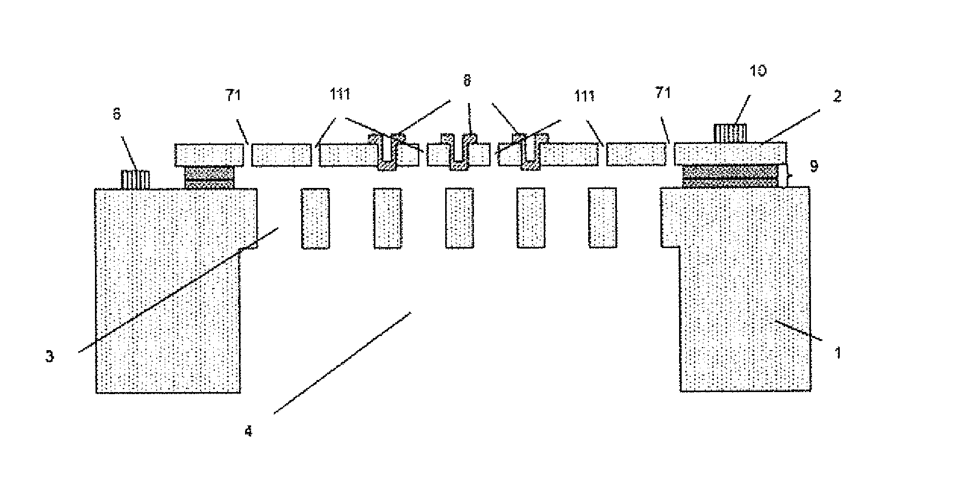
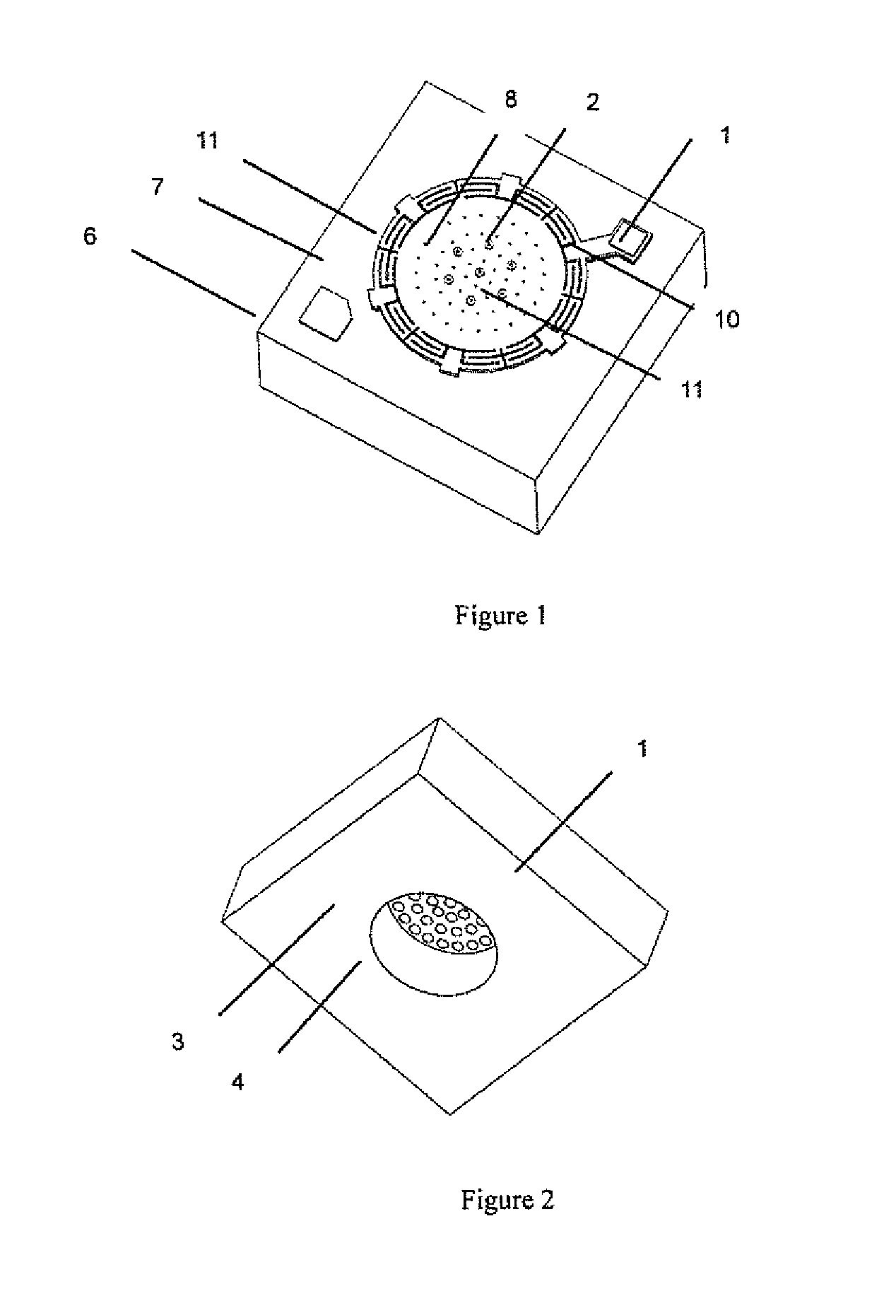
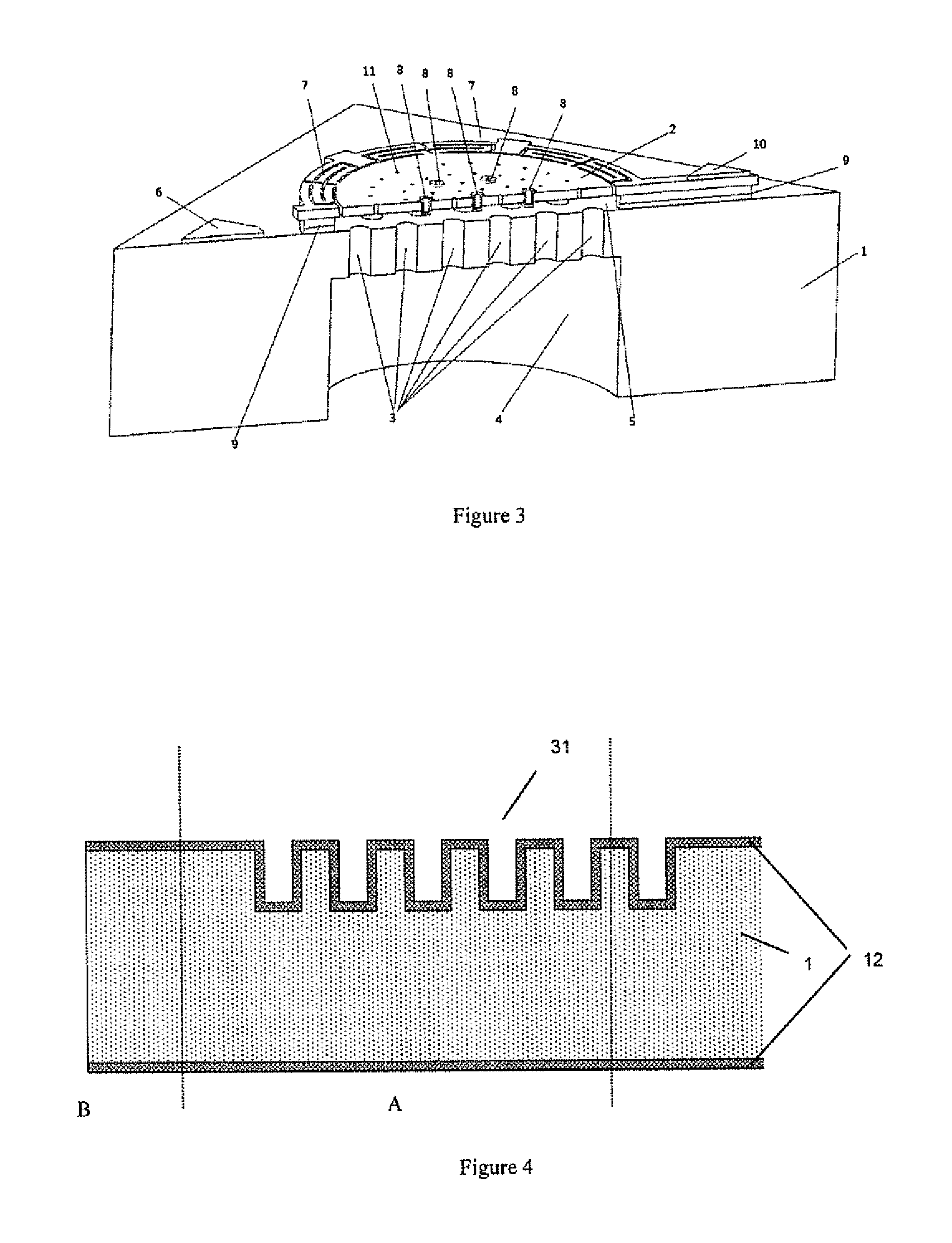
[0049]For overcoming the defects or drawbacks in prior arts, the present invention provides an MEMS silicon microphone and the fabrication method thereof. The technical features of the present invention bring positive effects that the processes for manufacturing MEMS silicon microphone is simplified while the sensitivity, reliability and production yield of MEMS silicon microphone is also improved.

[0050]For better understanding purpose, specific steps of the method and specific structures of the production will be described below to illustrate the technical features of the present invention. Some preferred embodiments are described specifically as follows. However, one of ordinary skills should b...


PUM

PropertyMeasurementUnit
thicknessaaaaaaaaaa
thicknessaaaaaaaaaa
thicknessaaaaaaaaaa

Abstract

This invention relates to the field of silicon microphone technology, more specifically, to a method for fabricating a MEMS microphone using multi-cavity SOT wafer by Si-Si fusion bonding technology, which comprises a multi-cavity silicon backplate and a monocrystalline silicon diaphragm, both are separated with a layer of silicon dioxide to form the capacitor of the MEMS microphone. The monocrystalline silicon diaphragm has advantages such as low residual stress and good uniformity, which increase the yield and sensitivity of MEMS silicon microphone; the diaphragm comprises tiny release-assistant holes, spring structures with anchors and bumps which can quickly release the residual stress and reduce the probability of stiction between the backplate and the silicon diaphragm. This structure will further improve yield and reliability of MEMS microphone. Therefore, this invention provides simple and reliable process for fabricating MEMS microphones with high sensitivity, good uniformity, excellent reliability and high yield.

Description

BACKGROUND OF THE INVENTION[0001]1. Field of the Invention[0002]The present invention relates to field of silicon microphone, more specifically, to an MEMS silicon microphone and a manufacture method thereof.[0003]2. Description of the Related Art[0004]Microphone converts human voice into a corresponding electrical signal, and is widely used in intelligent terminals like mobile phones, computers, telephones, cameras and camcorders.[0005]Advancement in development of MEMS (Microelectromechanical Systems) technology and process in the last thirty years and so, particularly development of silicon-based MEMS technology, has resulted in miniaturizing a number of sensors with low cost. Started in applications in high-end smart phones, MEMS silicon microphones have found their use broadening over the years in what has become a fast-growing and huge market.[0006]MEMS microphone mainly uses capacitive principle, comprising a diaphragm and a backplate with a few microns of air gap between the...

Claims


Application Information

Patent Timeline
Patent Type & Authority Applications(United States)
IPC IPC(8): B81C1/00H04R31/00H04R19/04B81B3/00H04R19/00
CPCB81C1/00158B81B3/0021H04R19/005H04R19/04H04R2201/003B81C2203/038B81B2201/0257B81B2203/0127B81C2201/0132H04R31/003
Inventor MIAO, JIANMIN
Owner MICROLINK SENSTECH SHANGHAI LTD
Why Eureka
Try Eureka