Method for denitrification of bypass exhaust gases in a plant for producing cement clinker

a technology of bypass exhaust gas and cement clinker, which is applied in the direction of separation process, furnace, lighting and heating apparatus, etc., can solve the problems of classical catalyst poison being masked by chemical reactions, the formation of dioxins and furans is not suppressed so well, and the formation of dioxins and furans is not suppressed. , the effect of less abrasion and poisoning

Active Publication Date: 2016-12-01
KHD HUMBOLDT WEDAG GMBH
View PDF3 Cites 9 Cited by
  • Summary
  • Abstract
  • Description
  • Claims
  • Application Information

AI Technical Summary

Problems solved by technology

In addition, heavy metals, halogens and sulfur and also carbon monoxide can be present in the bypass exhaust gas, although carbon monoxide is not normally to be expected in the bypass exhaust gas because of the oxidative conditions in the rotary tube furnace but is nevertheless occasionally found there, and these can poison the subsequent catalysts.
However, the partial reaction and hydrolysis involving a very complex sequential chemistry of short-lived and reactive compounds leads to the classical catalyst poisons being masked by chemical reactions.
However, they have the disadvantage that the formation of dioxins and furans is not suppressed so well.

Method used


Image

  • Method for denitrification of bypass exhaust gases in a plant for producing cement clinker
  • Method for denitrification of bypass exhaust gases in a plant for producing cement clinker
  • Method for denitrification of bypass exhaust gases in a plant for producing cement clinker

Examples


Embodiment Construction

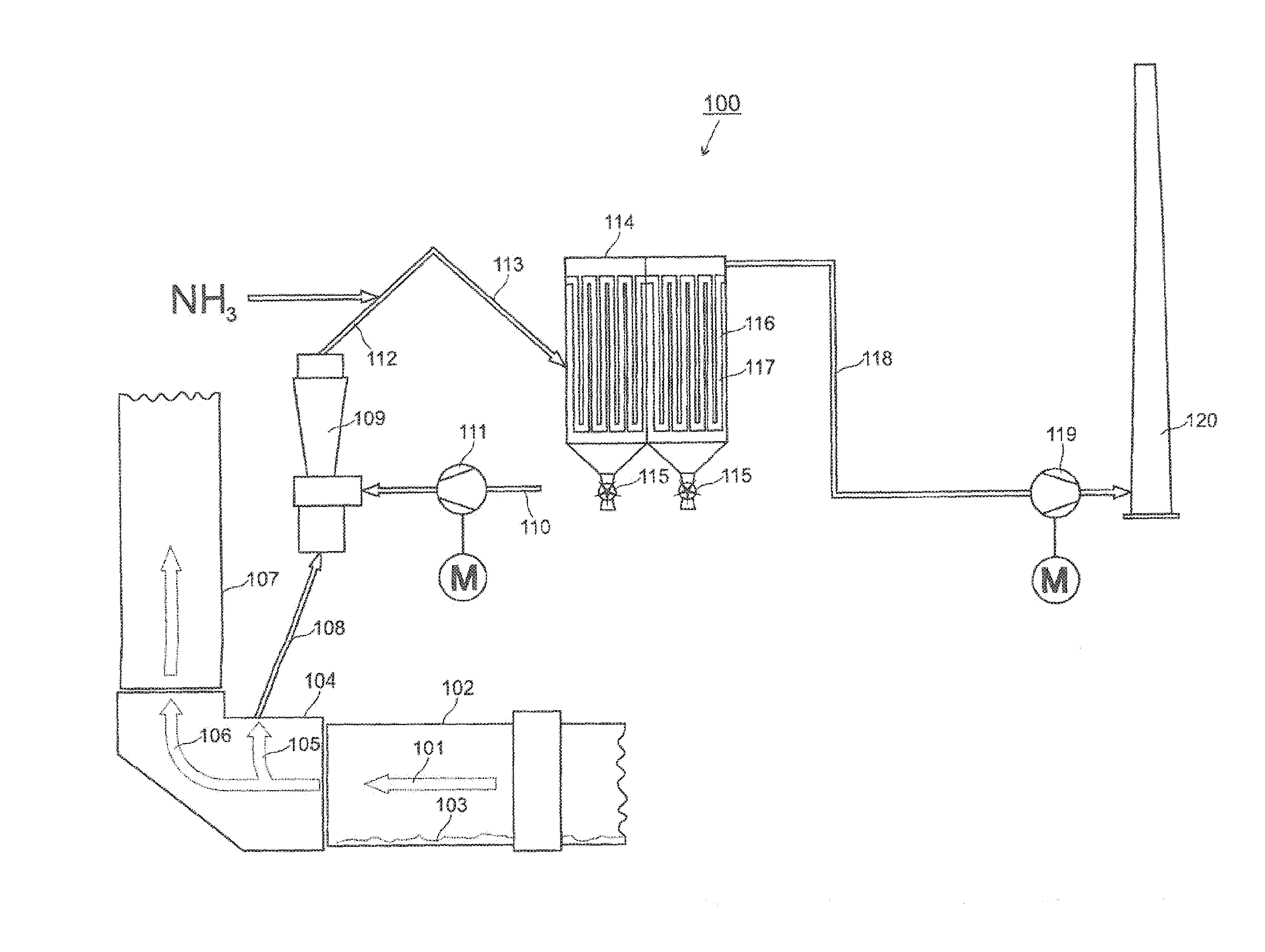
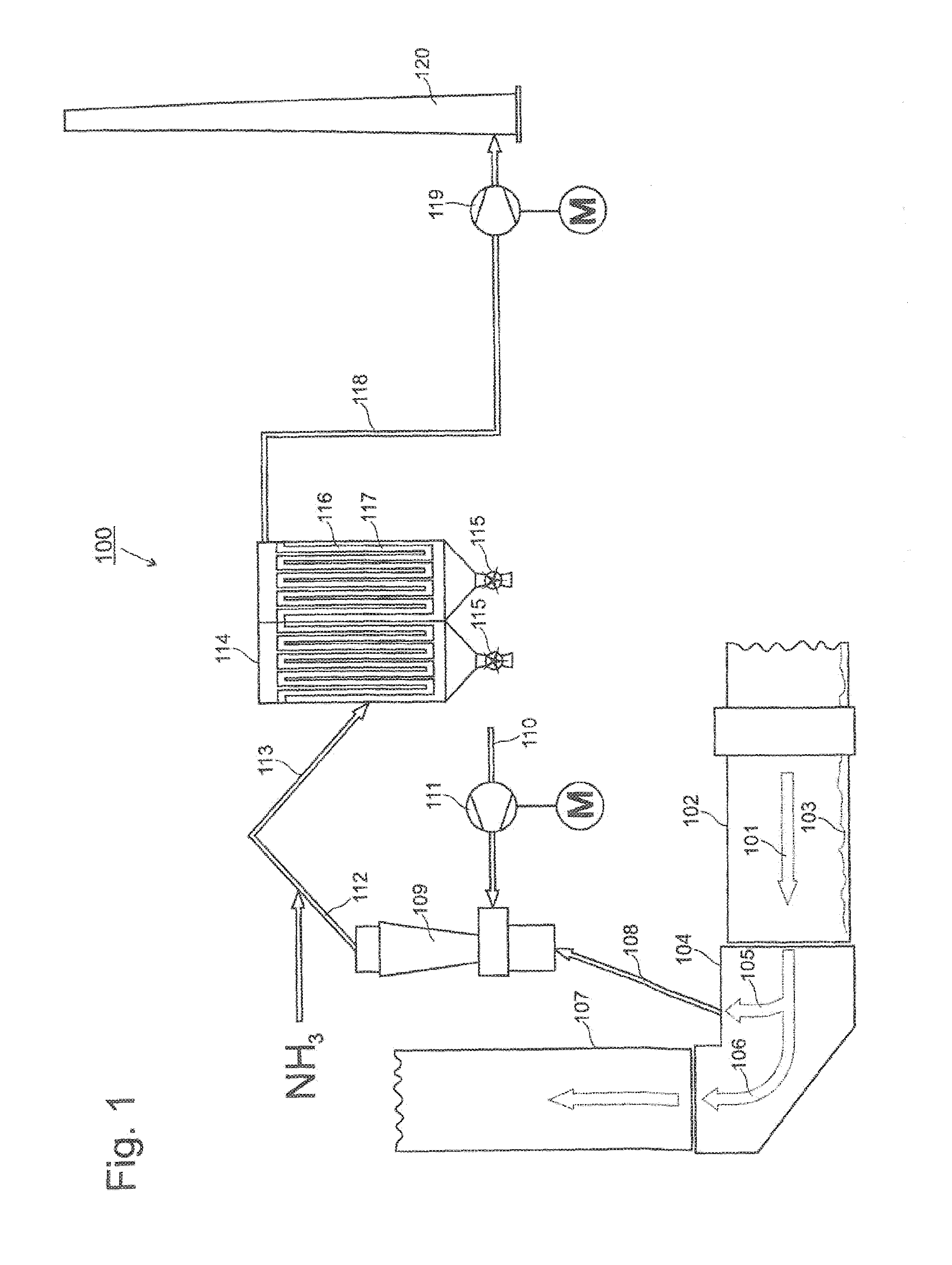
[0030]FIG. 1 shows a flow diagram 100 of a first plant configuration for carrying out the process of the invention. The in-principle structure of a plant for producing cement will here be assumed to be known. Hot combustion gases 101 pass through a rotary tube furnace 102 and heat this for sintering of the cement clinker 103 present in the rotary tube furnace 102. The combustion gases 101 leave the rotary tube furnace 102 at the left-hand end where the rotary tube furnace 102 opens into a rotary tube furnace inlet chamber 104. In the rotary tube furnace inlet chamber 104, the combustion gases cool to a great extent because they impinge there on gases from a heat exchanger (not shown here). On cooling of the combustion gases 101, alkali metal halides (LiF, LiCl, LiI, NaF, NaCl, NaI, KF, KCl, KI) and alkaline earth metal halides (MgF2, MgCl2, MgI2, CaF2, CaCl2, CaI2) and alkali metal and alkaline earth metal sulfates (Li2SO4, Na2SO4, K2SO4, MgSO4, CaSO4) condense and are, following th...


PUM

PropertyMeasurementUnit
temperatureaaaaaaaaaa

Abstract

Denitrifying bypass exhaust gases in a cement clinker producing plant. The plant comprises a rotary kiln connected to a calciner for the deacidification of raw material or to a rotary kiln riser shaft via a rotary kiln inlet chamber, and the bypass exhaust gas being drawn off in the region of the rotary kiln inlet chamber. The method comprises: cooling the bypass gas to between 260 C and 400 C in a cooling device, injecting an ammonia-, urea-, and / or ammonium-containing substance into the cooled bypass gas, introducing the cooled and mixed bypass gas into a ceramic filter system to filter out any halide and sulfate of the alkali metals and alkaline-earth metals precipitated during cooling the gas, and any nitrogen not reacted by the injected substances is chemically selectively reduced over a catalytic converter which is located in or directly downstream of the ceramic filter system.

Description

CROSS-REFERENCES TO RELATED APPLICATIONS[0001]This application claims the benefit of the German patent application No. 10 2013 016 701.9 filed on Oct. 8, 2013, the entire disclosures of which are incorporated herein by way of reference.BACKGROUND OF THE INVENTION[0002]The invention relates to a process for the denitrification of bypass exhaust gases in a plant for producing cement clinker, where the plant has, in the gas flow direction, a rotary tube furnace for sintering of the cement clinker, and where the rotary tube furnace is connected via a rotary tube furnace inlet chamber to a calciner for deacidification of raw meal or to a rotary tube furnace riser shaft, and where the bypass exhaust gas is taken off in the region of the rotary tube furnace inlet chamber.[0003]To produce cement, silicate- (SiO44−) and carbonate-containing (CO32−) rock is milled, formally freed of carbon dioxide (CO2) by deacidification of the carbonate (CO32−) to the oxide (—O) (in the form of quicklime, C...

Claims


Application Information

Patent Timeline
Patent Type & Authority Applications(United States)
IPC IPC(8): C04B7/36F27D17/00C04B7/43F27B7/20B01D53/86B01D53/90
CPCC04B7/365B01D2258/0233B01D53/8628B01D53/8668B01D53/90C04B7/43F27B7/20F27D17/008B01D2255/20707B01D2255/20723B01D2255/20776B01D2255/915B01D2251/2062B01D2251/2065B01D2251/2067B01D53/8631B01D2251/206B01D2257/404C04B7/60B01D53/8621C04B7/36
Inventor SCHUERMANN, HEIKO
Owner KHD HUMBOLDT WEDAG GMBH
Why Eureka
Try Eureka