
High-Efficiency N-Type Bifacial Solar Cell

a solar cell, high-efficiency technology, applied in the direction of basic electric elements, electrical apparatus, semiconductor devices, etc., can solve the problems of high cost, high cost, and high cost of p-type solar cells, and achieve the effect of improving the open-circuit voltage of the cell

Inactive Publication Date: 2016-12-01
SHANGHAI SHENZHOU NEW ENERGY DEV
View PDF3 Cites 6 Cited by
  • Summary
  • Abstract
  • Description
  • Claims
  • Application Information

AI Technical Summary

Benefits of technology

The present invention is a high-efficiency N-type bifacial solar cell that provides better performance and generates more power in the morning and evening compared to currently available P-type bifacial cells. The cell has a bifacial optical-electrical conversion effect, where carriers collected from both sides of the cell contribute to the power output. The heavy phosphorus doping in the back side of the solar cell avoids cell warping and allows for a thinner silicon substrate. A polished passivation layer and an N+ passivation layer increase the open-circuit voltage of the cell and further improve the conversion efficiency. The N-type cell base is an N-type silicon wafer doped with phosphorus, which has longer minority carriers life time compared to P-type solar cells.

Problems solved by technology

However, it is not easy to achieve large-scale production of N-type high-efficiency cells.
The technical procedures for obtaining high-efficiency N-type solar cells are much complicated than those for P-type solar cells and are subject to severe technical requirements.
In addition to complicated processing, the above two cells require high-quality silicon materials and surface passivation.
No matter the front surface or the back surface, printing alignment problem exists in manufacture of bifacial cells and has a higher demand in production and the technicians.
Furthermore, the procedure of cleaning corrosive paste consumes a large amount of water and generates a large amount of toxic pollutants.

Method used


Image

  • High-Efficiency N-Type Bifacial Solar Cell
  • High-Efficiency N-Type Bifacial Solar Cell

Examples


Embodiment Construction

[0024]To more clearly understand the objectives, technical solutions, and advantages of the present invention, the present invention will be further described in connection with the accompanying drawings and embodiments. It is noted that the embodiments described herein are merely used to explain the present invention and should not be used to restrict the present invention.

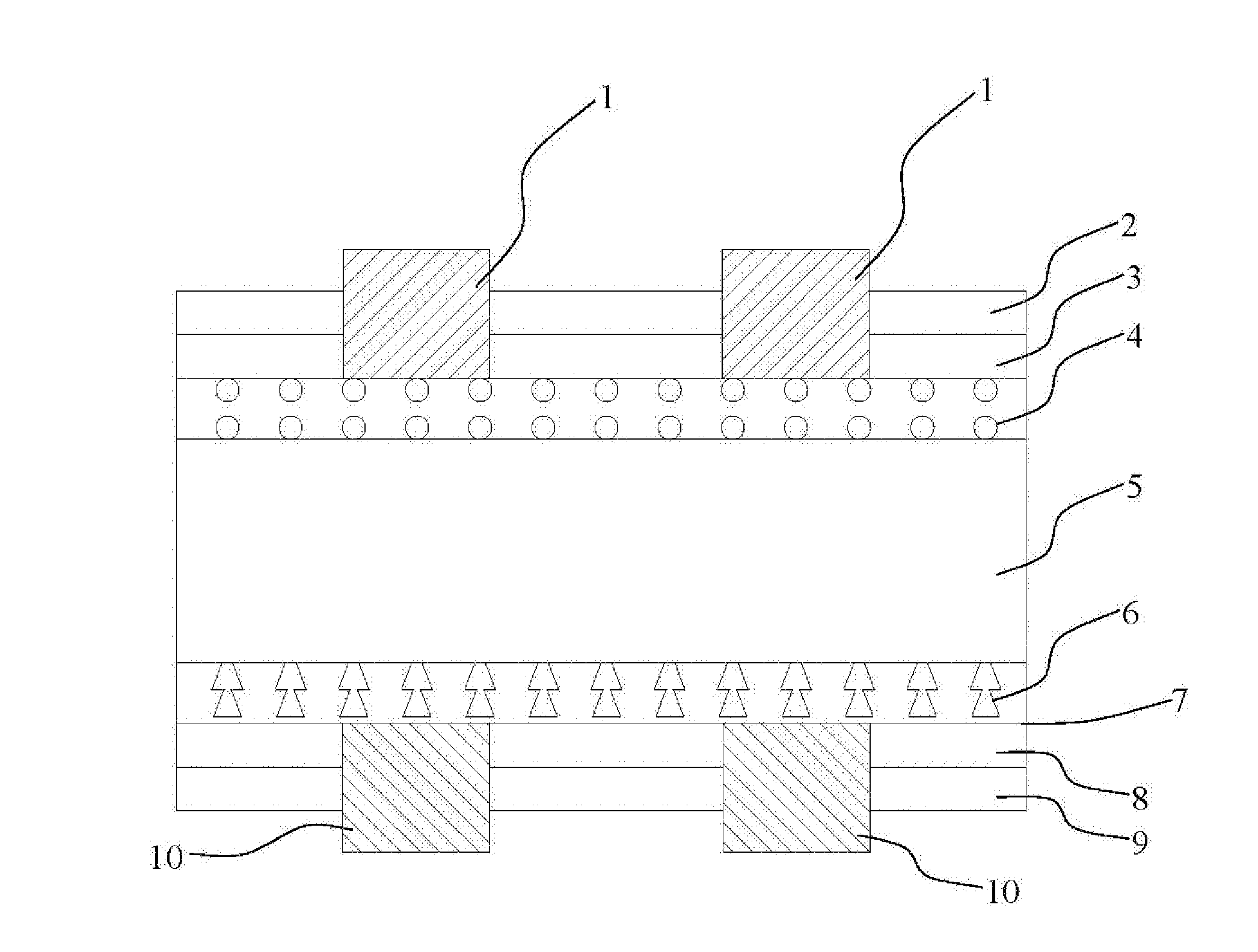
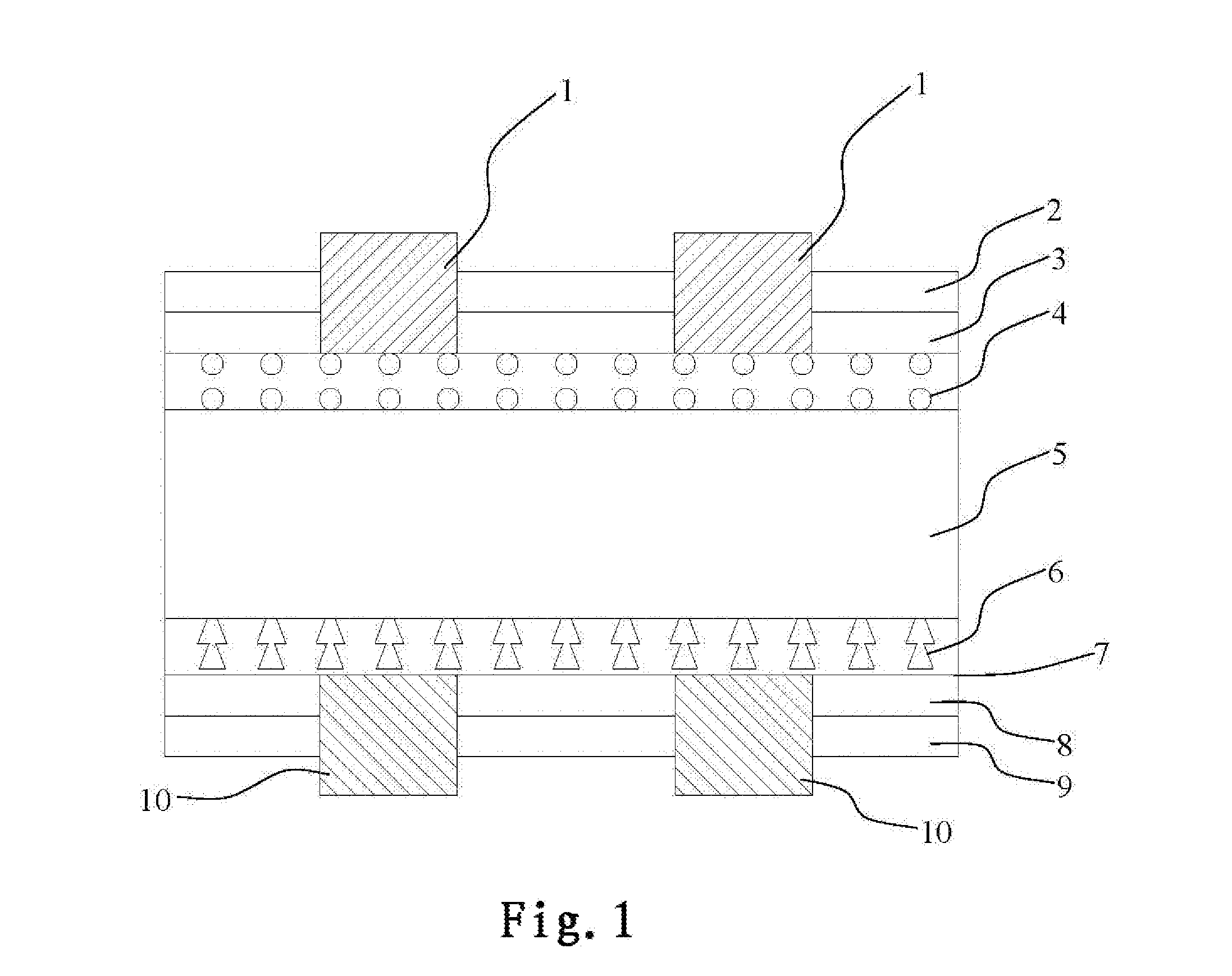
[0025]Please refer to FIG. 1. FIG. 1 is a diagrammatic structural view of a high-efficiency N-type bifacial solar cell according to the present invention. As shown in FIG. 1, the high-efficiency N-type bifacial solar cell according to the present invention includes:

[0026]an N-type cell base 5 including a structuralized surface;

[0027]a P-type doped region 4 formed on a front surface of the N-type cell base;

[0028]a polished passivation layer 7 formed on a back surface of the N-type cell base 5 by etching;

[0029]an N+ passivation layer 6 formed by doping phosphorus into a top portion of the polished passivation layer...


PUM


Abstract

A high-efficiency N-type bifacial solar cell including: an N-type cell base including a structuralized surface; a P-type doped region formed on a front surface of the N-type cell base; a polished passivation layer formed on a back surface of the N-type cell base by etching; an N+ passivation layer formed by doping phosphorus into a top portion of the polished passivation layer adjacent to the N-type cell base; a first silicon dioxide layer formed on the P-type doped region and a second silicon dioxide layer disposed on the N+ passivation layer; a first silicon nitride antireflection layer formed on the first silicon dioxide layer and a second silicon nitride antireflection layer formed on the second silicon dioxide layer; and a first metal electrode formed on the front surface of the N-type cell base and a second metal electrode formed on the back surface of the N-type cell base.

Description

FIELD OF THE INVENTION[0001]The present invention relates to the field of solar cell manufacturing technology and, more particularly, to a high-efficiency N-type bifacial solar cell.DESCRIPTION OF THE PRIOR ART[0002]Most of crystalline silicon solar cells on the market use P-type silicon wafers, i.e., silicon wafers doped with boron. Nevertheless, N-type cells produced from N-type silicon wafers have received more attention in recent years and have been used to make N-type solar cells. N-type silicon wafers are silicon wafers doped with phosphorus. Since N-type silicon wafers have longer minority carriers life time, the resultant cells have higher optical-electrical conversion efficiency. Furthermore, N-type cells have a higher tolerance to metal pollution and have better durability and stability. N-type silicon wafers doped with phosphorus have no boron-oxygen pairs, and the cells have no photoluminescence degradation caused by the boron-oxygen pairs. Due to these advantages of N-t...

Claims


Application Information

Patent Timeline
IPC IPC(8): H01L31/068H01L31/0232H01L31/0224H01L31/0216H01L31/0288
CPCH01L31/0684H01L31/02168H01L31/02327H01L31/022425H01L31/0288H01L31/02167H01L31/02363H01L31/068Y02E10/547
Inventor ZHENG, FEIZHANG, ZHONGWEISHI, LEIRUAN, ZHONGLITAO, ZHIHUAZHAO, YUXUE
Owner SHANGHAI SHENZHOU NEW ENERGY DEV
Learn More