Adaptive control for charged particle beam processing

a technology of charged particle and beam processing, applied in the direction of electric discharge tubes, chemical vapor deposition coatings, coatings, etc., can solve the problems of requiring significant user intervention for two and three dimensional printing with current beam systems, and affecting the processing efficiency of charged particle beams. achieve the effect of improving the beam processing

Inactive Publication Date: 2017-01-05
FEI CO
View PDF4 Cites 6 Cited by
  • Summary
  • Abstract
  • Description
  • Claims
  • Application Information

AI Technical Summary

Benefits of technology

[0012]An object of the invention is to provide improved beam

Problems solved by technology

Changing the aperture typically requires physically moving a new aperture into the beam path and centering it, which takes some time.
When the machine operator desires to form a pattern having both large and small features, the operator needs to select a beam that provides sufficient resolution to produce the finer features, which results in an excessive time for forming larger features that do not require fine resolution.
However, two and three dimensional printing with current beam systems require significant user intervention and are limited to thin two-dimensional or simple three-dimensiona

Method used


Image

  • Adaptive control for charged particle beam processing
  • Adaptive control for charged particle beam processing
  • Adaptive control for charged particle beam processing

Examples


Embodiment Construction

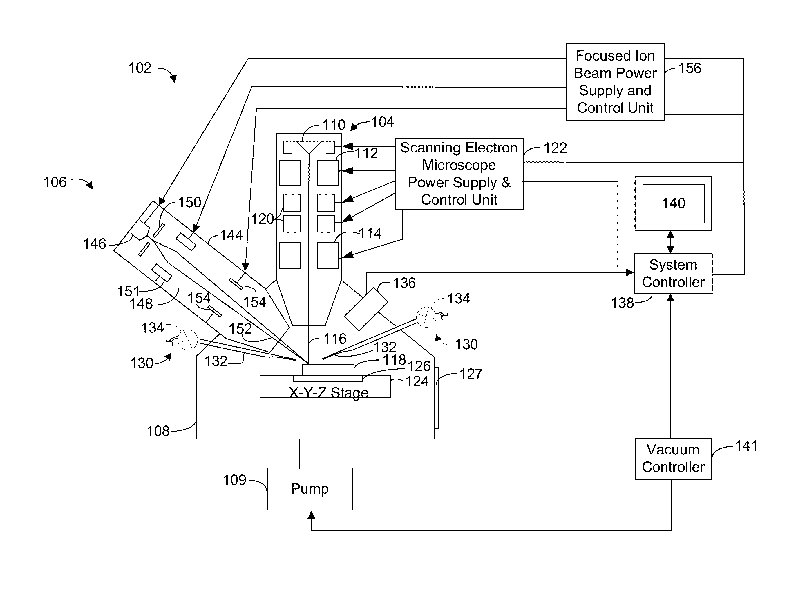
[0034]FIG. 1 shows a dual beam system 102 that can be used to carry out embodiments of the invention. Suitable beam systems are commercially available, for example, from FEI Company, Hillsboro, Oregon, the assignee of the present invention. While an example of suitable hardware is provided below, the invention is not limited to being implemented in any particular type of hardware.

[0035]Dual beam system 102 has a vertically mounted electron beam column 104, and a focused ion beam (FIB) column 106 mounted at an angle of approximately 52 degrees from the vertical on an evacuable specimen chamber 108. The specimen chamber may be evacuated by pump system 109, which typically includes one or more, or a combination of, a turbo-molecular pump, oil diffusion pumps, ion getter pumps, scroll pumps, or other known pumping means.

[0036]The electron beam column 104 includes an electron source 110, such as a Schottky emitter or a cold field emitter, for producing electrons, and electron-optical len...


PUM

PropertyMeasurementUnit
Structureaaaaaaaaaa
Sizeaaaaaaaaaa
Speedaaaaaaaaaa

Abstract

An improved process control for a charged beam system is provided that allows the capability of accurately producing complex two and three dimensional structures from a computer generated model in a material deposition process. The process control actively monitors the material deposition process and makes corrective adjustments as necessary to produce a pattern or structure that is within an acceptable tolerance range with little or no user intervention. The process control includes a data base containing information directed to properties of a specific pattern or structure and uses an algorithm to instruct the beam system during the material deposition process. Feedback through various means such as image recognition, chamber pressure readings, and EDS signal can be used to instruct the system to make automatic system modifications, such as, beam and gas parameters, or other modifications to the pattern during a material deposition run.

Description

TECHNICAL FIELD OF THE INVENTION[0001]The present invention relates generally to a method and apparatus for depositing material in a pattern.BACKGROUND OF THE INVENTION[0002]Beam systems, such as electron beam systems, ion beam systems, laser beam systems, cluster beam systems, and neutral particle beam systems, are used to create features on a surface by etching or depositing material. Focused beams are used to remove material from a sample and to deposit material onto the sample. Material can be removed by sputtering, in which the momentum of the particles in the beam physically knock atom or molecules from the sample surface.[0003]A particle or laser beam can be used to induce a chemical reaction. In some cases, the beam induces decomposition of a precursor gas. The precursor gas is preferably stable so that it does not react with the work piece away from the beam impact area. The resolution of the deposit or etching is determined by the beam diameter and region of interaction be...

Claims


Application Information

Patent Timeline
IPC IPC(8): C23C16/48C23C16/56C23C16/52
CPCC23C16/047C23C16/4418C23C16/52H01J2237/30472H01J2237/31749H01J2237/30416H01J37/3023H01J2237/30455H01J37/3026H01J37/3178H01J2237/31735H01J37/304H01J37/317H01J37/08
Inventor STRAW, MARCUSRUE, CHADRANDOLPH, STEVENBOTMAN, AURELIEN PHILIPPE JEAN MACLOUCHANDLER, CLIVE D.UTLAUT, MARK W.
Owner FEI CO
Why Eureka
Try Eureka