
Ferroelectric nanocomposite based dielectric inks for reconfigurable RF and microwave applications

a nano-composite, dielectric ink technology, applied in the direction of inks, waveguides, waveguide devices, etc., can solve the problems of inability to characterization of bst/polymer dielectrics at frequencies above 1 ghz, inability to use bst in the form of ceramic films, etc., and achieve the effect of low loss tangen

Active Publication Date: 2017-01-12
UNIV OF MASSACHUSETTS
View PDF13 Cites 22 Cited by
  • Summary
  • Abstract
  • Description
  • Claims
  • Application Information

AI Technical Summary

Benefits of technology

The invention is a liquid ink that includes pre-sintered perovskite oxide particles dispersed in a thermoplastic polymer. The ink has a low loss tangent at high frequencies and a low viscosity. The invention also includes a dispersant to disperse the particles in the polymer. The invention can be used in various applications such as inkjet printing, flexible electronics, and antennas. The invention also includes a composition of matter that includes the pre-sintered perovskite oxide particles embedded in a thermoplastic polymer. The invention also includes an apparatus with electrically conductive structures and a filler material containing the pre-sintered perovskite oxide particles. The invention allows for tunable responses and can be controlled with applied voltage.

Problems solved by technology

From the printed electronics perspective, utilizing BST in the form of ceramic films is impractical since they are brittle in nature and their fabrication require sintering at extremely high temperatures (>850° C.
), which is unfeasible on plastic substrates, as well as in many semiconductor processing applications.
However, these studies utilized plastic extrusion and injection molding.
Moreover, none of these studies reported characterization of BST / polymer dielectrics at frequencies above 1 GHz.

Method used


Image

  • Ferroelectric nanocomposite based dielectric inks for reconfigurable RF and microwave applications
  • Ferroelectric nanocomposite based dielectric inks for reconfigurable RF and microwave applications
  • Ferroelectric nanocomposite based dielectric inks for reconfigurable RF and microwave applications

Examples


Embodiment Construction

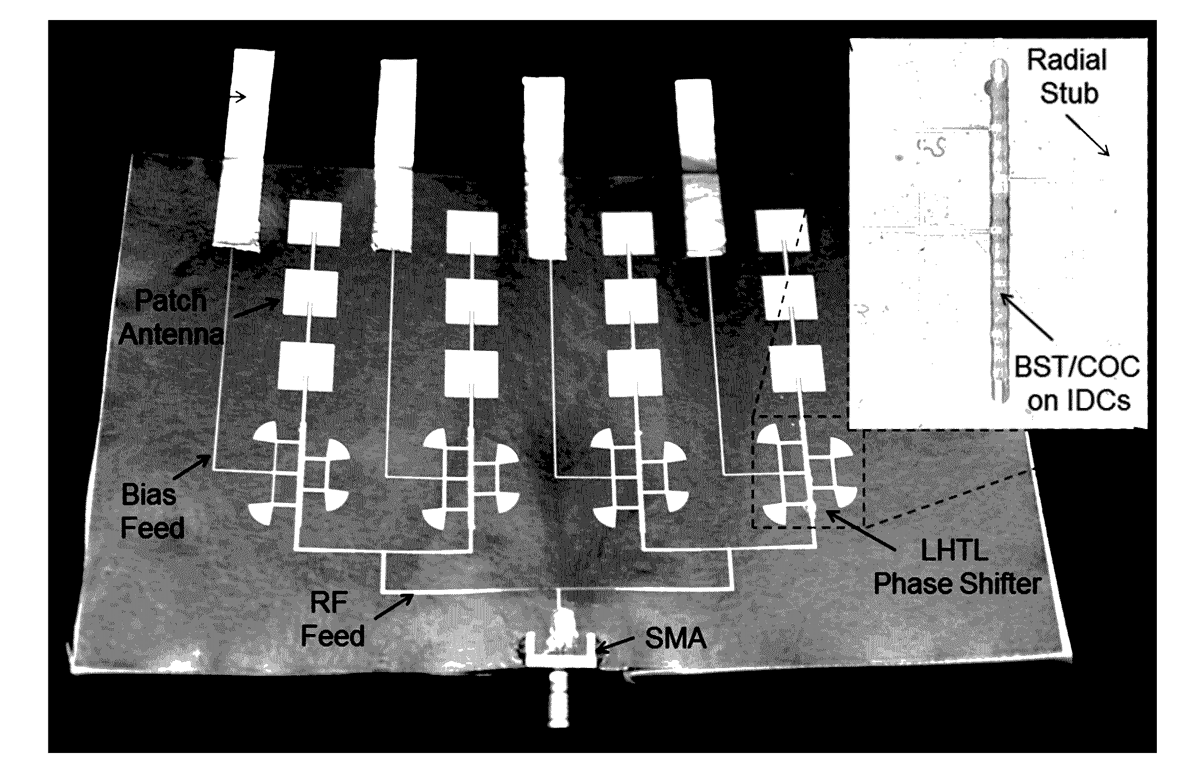
[0054]A fully printed varactor and a phase shifter using direct ink writing methodologies are described. A novel ferroelectric ink was developed and was employed using direct-ink writing techniques to print high dielectric constant, low loss, and electrostatically-tunable dielectrics on plastic substrates. It is believes that similar methods can be used on substrates that are not flexible, such as substrates comprising semiconductor materials or ceramics and the like. The dielectric is based on multiphase Barium Strontium Titanate (BST) / polymer composite made by suspending pre-sintered nano / submicron-sized particles of BST in a thermoplastic polymer, namely Cyclic Olefin Copolymer (COC). After printing with the ink, a low temperature curing process was performed at temperatures below 200° C., a temperature too low to sinter BST. RF measurements and characterizations showed that the sinter-less dielectric had a very high relative permittivity of εr=40 and a very low dielectric loss o...


PUM

PropertyMeasurementUnit
size distributionaaaaaaaaaa
temperaturesaaaaaaaaaa
sizeaaaaaaaaaa

Abstract

A novel ferroelectric ink comprising multiphase Barium Strontium Titanate (BST) in a polymer composite is described. The ink can be employed using direct-ink writing techniques to print high dielectric constant, low loss, and electrostatically-tunable dielectrics on substrates. The substrates can be flexible such as plastics or rigid, such as substrates comprising semiconductor materials or ceramics and the like. The dielectric ink is made by suspending pre-sintered nano / submicron-sized particles of BST in a thermoplastic polymer with a solvent. After printing with the ink, a low temperature curing process is performed at temperatures below 200° C., a temperature too low to sinter BST. Fully printed devices, such as a varactor and a phase shifter using direct ink writing methodologies are described.

Description

CROSS-REFERENCE TO RELATED APPLICATIONS[0001]This application claims priority to and the benefit of co-pending U.S. provisional patent application Ser. No. 62 / 189,054, filed Jul. 6, 2015, and of co-pending U.S. provisional patent application Ser. No. 62 / 357,985, filed Jul. 2, 2016, and of co-pending U.S. provisional patent application Ser. No. 62 / 358,705, filed Jul. 6, 2016, each of which applications is incorporated herein by reference in its entirety.THE NAMES OF THE PARTIES TO A JOINT RESEARCH AGREEMENT[0002]This invention resulted from work under a joint research agreement between the University of Massachusetts Lowell and the Raytheon Company.FIELD OF THE INVENTION[0003]The invention relates to ferroelectric inks in general and particularly to ferroelectric inks that provide tunability.BACKGROUND OF THE INVENTION[0004]Enabled by freedom and capacity of printed electronics with the promises of low cost and rapid manufacturing of light weight and flexible electronic circuits, pri...

Claims


Application Information

Patent Timeline
Patent Type & Authority Applications(United States)
IPC IPC(8): C09D11/102C09D11/033H05K1/02C09D11/03
CPCC09D11/102C09D11/03H05K1/028H05K1/0246C09D11/033H01P1/181H01P3/00H01Q21/065H05K1/16H05K1/162H05K2201/086
Inventor HAGHZADEH, MAHDIAKYURTLU, ALKIMARMIENTO, CRAIG
Owner UNIV OF MASSACHUSETTS
Learn More