Method for preparing transition metal phosphide

Active Publication Date: 2017-01-19
AGENCY FOR SCI TECH & RES
View PDF9 Cites 20 Cited by
  • Summary
  • Abstract
  • Description
  • Claims
  • Application Information

AI Technical Summary

Benefits of technology

[0015]Advantageously, the method of producing hydrogen can be carried out at atmospheric pressure and/or at room temperature; hence the electrocatalytic process can be scaled-up easily.
[0016]Advantageously, when coupled

Problems solved by technology

Reaction (i) is the rate limiting step in overall water splitting process because it has higher energy barrier.
Without an efficient catalyst, a significant overpotential is required for water oxidation or reduction, resulting in a low efficiency process.
However, the electrocatalytic efficiency of these reported catalysts has not reached the lev

Method used


Image

  • Method for preparing transition metal phosphide
  • Method for preparing transition metal phosphide
  • Method for preparing transition metal phosphide

Examples


example 1

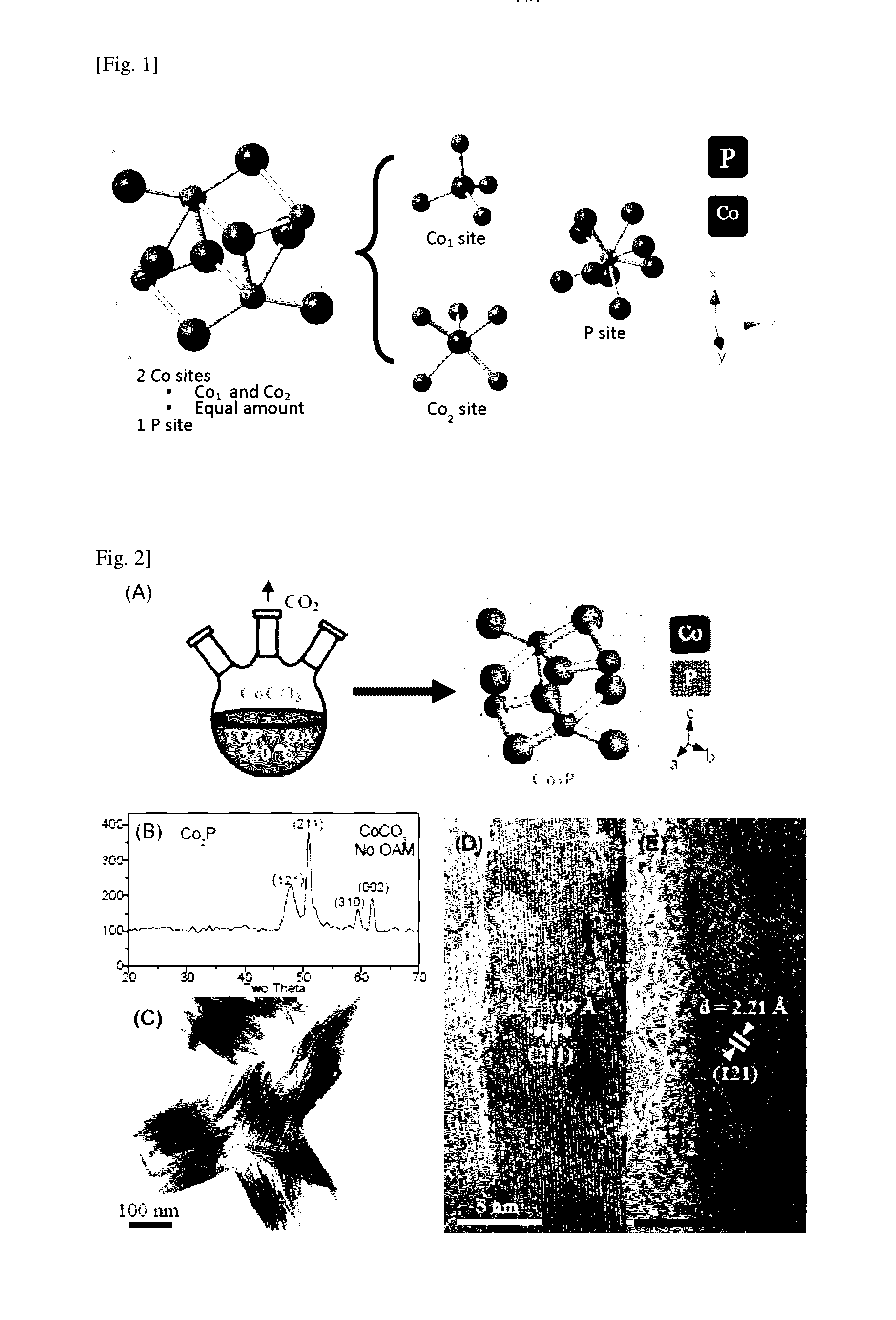
Synthesis of Cobalt Phosphide A

[0083]Cobalt phosphide A was prepared by first dissolving 1.5 mmol of cobalt (II) carbonate (CoCO3, 99%, obtained from Sigma-Aldrich of Missouri of the United States of America) in 4.5 mmol of oleic acid (OA, CH3(CH2)7CH═CH(CH2)7COOH, cis 70%, obtained from Sigma-Aldrich of Missouri of the United States of America) and 5 ml of TOP ([CH3(CH2)7]3P, 90%, obtained from Sigma-Aldrich of Missouri of the United States of America) forming a mixture. The temperature of the mixture was then adjusted to 110° C. with vigorous magnetic stirring followed by degassing in vacuum for 15 minutes. At this temperature, cobalt (II) carbonate dissolved in TOP and blended with oleic acid to form cobalt oleate and by-product CO2. The degassing procedure is crucial to prevent oxygen to enter into the reaction chamber thereby inhibiting the reaction. The post-degassing mixture exhibited a homogeneous translucent violet color, indicating a complete dissolution of Co2+ and the fo...

example 2

Synthesis of Cobalt Phosphide B

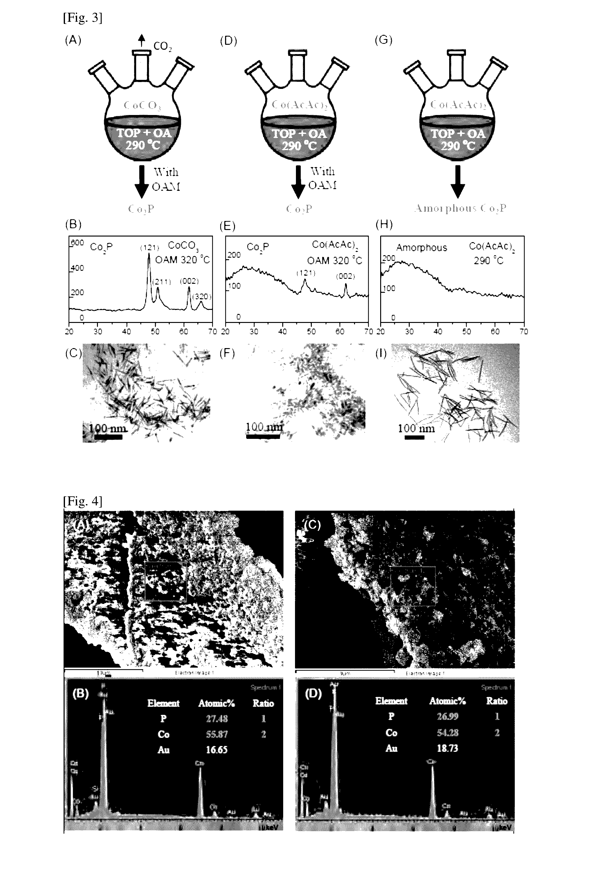
[0085]To investigate the influence of temperature and different reagents on the chemical phase and the shape or size of the synthesized cobalt phosphide, cobalt phosphide B was prepared using the same method as described in Example 1 but with final temperature set to 290° C. instead of 320° C. and with adding 3 mmol of oleylamine (denoted as OAM thereafter, CH3(CH2)7CH═CH(CH2)7CH2NH2, cis 70%, obtained from Sigma-Aldrich of Missouri of the United States of America) to the reaction mixture (see FIG. 3(A)).

[0086]TEM and XRD studies were carried out to investigate the properties of the nanostructures obtained. As revealed in FIGS. 3(B) and 3(C), the XRD pattern of the nanostructures synthesized using cobalt (II) carbonate in 4.5 mmol of oleic acid, 5 ml of TOP with the addition of 3 mmol of oleylamine features dicobalt phosphide phase. It is surprisingly found that the crystallinity of nanostructures was reduced when the temperature is decreased to 290° C...

example 3

Synthesis of Cobalt Phosphide C

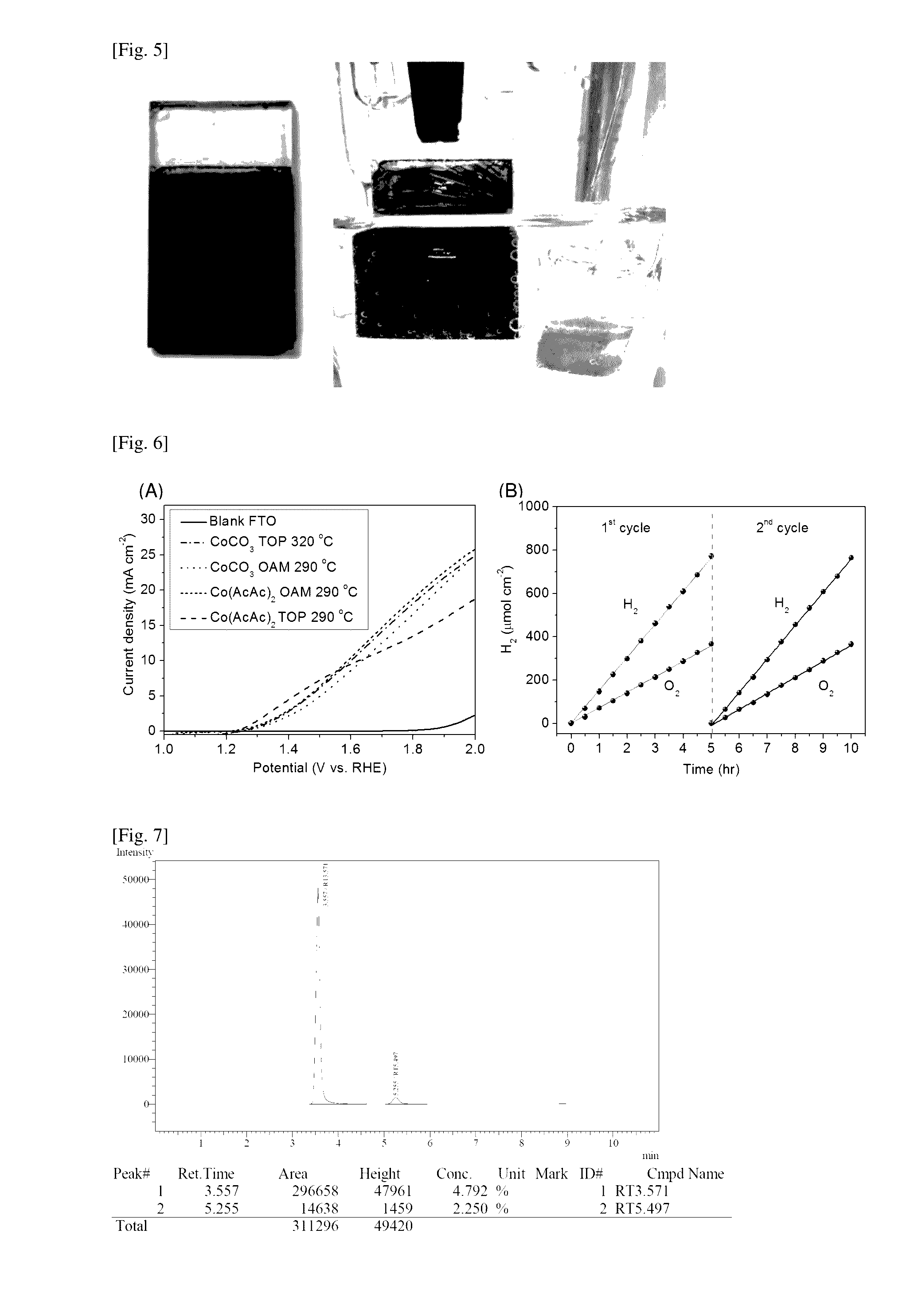
[0087]Here, cobalt phosphide C was synthesized using the method as described in Example 1. Cobalt (II) acetylacetate (Co(AcAc)2, 99%, obtained from Sigma-Aldrich of Missouri of the United States of America) was used as the cobalt (II) salt instead of cobalt (II) carbonate (see FIG. 3(G)). The final temperature of the reaction mixture was set to 290° C. XRD analysis depicted in FIG. 3(H) shows an amorphous pattern with no recognizable peaks. Further, inspection of SEM energy-dispersive X-ray spectroscopy (EDX) analysis depicted in FIG. 4(C) and FIG. 4(D) confirms that the chemical composition of cobalt phosphide C had the atomic ratio of cobalt to phosphorous about 2 to 1. This example demonstrates the synthesis of armorphous dicobalt phosphide nanostructures. The morphology of cobalt phosphide C was nanowire (FIG. 3(I)).


PUM


Abstract

There is provided a method of preparing transition metal phosphide comprising the step of mixing a solution of a transition metal precursor and a phosphorous precursor under conditions to form the transition metal phosphide. There is also provided a transition metal phosphide particle made according to the method as defined herein. There is additionally provided a method of preparing a transition metal phosphide-based electrode used for producing hydrogen in the electrolysis of water.

Description

TECHNICAL FIELD[0001]The present invention generally relates to a method for preparing a transition metal phosphide. The present invention also relates to a transition metal phosphide particle as prepared herein, a method of preparing a transition metal phosphide-based electrode used for producing hydrogen in the electrolysis of water.BACKGROUND ART[0002]Hydrogen production from water splitting is a promising source of clean energy that has the potential to mitigate the crises of fossil fuel dependence and global warming. Today, the industry technology for the hydrogen production is predominantly the steam reforming from hydrocarbons, such as methane, at high temperature up to 1000° C., followed by a water-gas shift reaction. However, this industry process generates one carbon dioxide molecule for every four hydrogen molecules produced. Therefore, it is necessary to develop an alternative green and sustainable energy technology.[0003]Electrolytic water splitting represents a prospec...

Claims


Application Information

Patent Timeline
IPC IPC(8): C01B25/08C25B11/04C25B1/04
CPCC01B25/08C25B11/04C25B1/04Y02P20/133Y02E60/36
Inventor ZHANG, SHUANG-YUANTEE, SI YINHAN, MING-YONGSHAH, KWOK WEICHUA, CHIN SHENGCHI, DONGZHIHOR, ANDY
Owner AGENCY FOR SCI TECH & RES
Why Eureka
Try Eureka