High-speed germanium pin photodiode

a germanium pin and photodiode technology, applied in the field of diodes, can solve the problems of limiting the responsivity of the diodes, high responsivity and high bandwidth, and achieve the effect of low contact resistan

Active Publication Date: 2017-01-26
IHP GMBH INNOVATIONS FOR HIGH PERFORMANCE MICROELECTRONICS LEIBNIZ INST FUR INNOVATIVE
View PDF0 Cites 8 Cited by
  • Summary
  • Abstract
  • Description
  • Claims
  • Application Information

AI Technical Summary

Benefits of technology

[0022]The field distribution is further improved in a variant in which the p- and n-doping fronts continue beyond the germanium region in the direction of the substrate interior, that is to say vertically downward as far as the bottom edge of the waveguide, and separate the p- and n-doped waveguide regions from an intrinsic waveguide region.
[0023]In yet another embodiment, the extensions extend in the lateral direction from the germanium region to an (outer) diode edge defined by an insulator and lie on top of a silicon oxide layer. This embodiment advantageously allows direct contact between metal regions and the germanium re

Problems solved by technology

This results in losses because of light absorption by the metal electrodes and due to light absorption by free charge carriers in the doped germanium regions, thus limiting the responsivit

Method used


Image

  • High-speed germanium pin photodiode
  • High-speed germanium pin photodiode
  • High-speed germanium pin photodiode

Examples


first embodiment

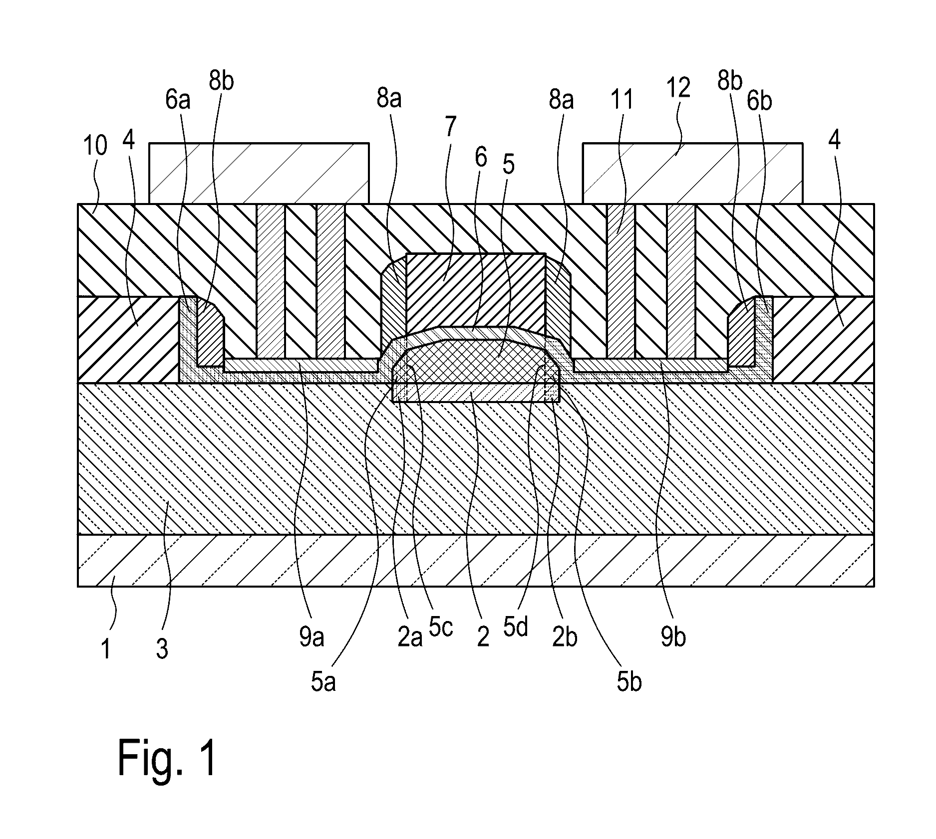
[0050]FIG. 1 illustrates a PIN photodiode according to the invention. On a monocrystalline silicon waveguide consisting of p- and n-doped regions 2a and 2b and intrinsic region 2 and framed laterally and from below by a silicon dioxide layer 3 vertically adjoining a silicon substrate 1, there is a germanium layer containing doped regions 5a and 5b and intrinsic region 5. This germanium layer is covered with a silicon layer consisting of doped regions 6a and 6b and an undoped region 6. As essential aspect for the PIN photodiode according to the invention is that the silicon waveguide below the germanium layer does not project laterally beyond the latter. The entire diode structure is laterally enclosed by an insulator layer 4, preferably by a silicon oxide layer. The diode structure is also covered with an insulating strip 7, which, as explained in more detail below, allows self-aligned production of intrinsic regions 2, 5 and 6 with p- and n-doped regions 2a, 2b, 5a, 5b, 6a and 6b. ...

second embodiment

[0061]A process for producing the germanium PIN photodiode according to the invention shall now be described.

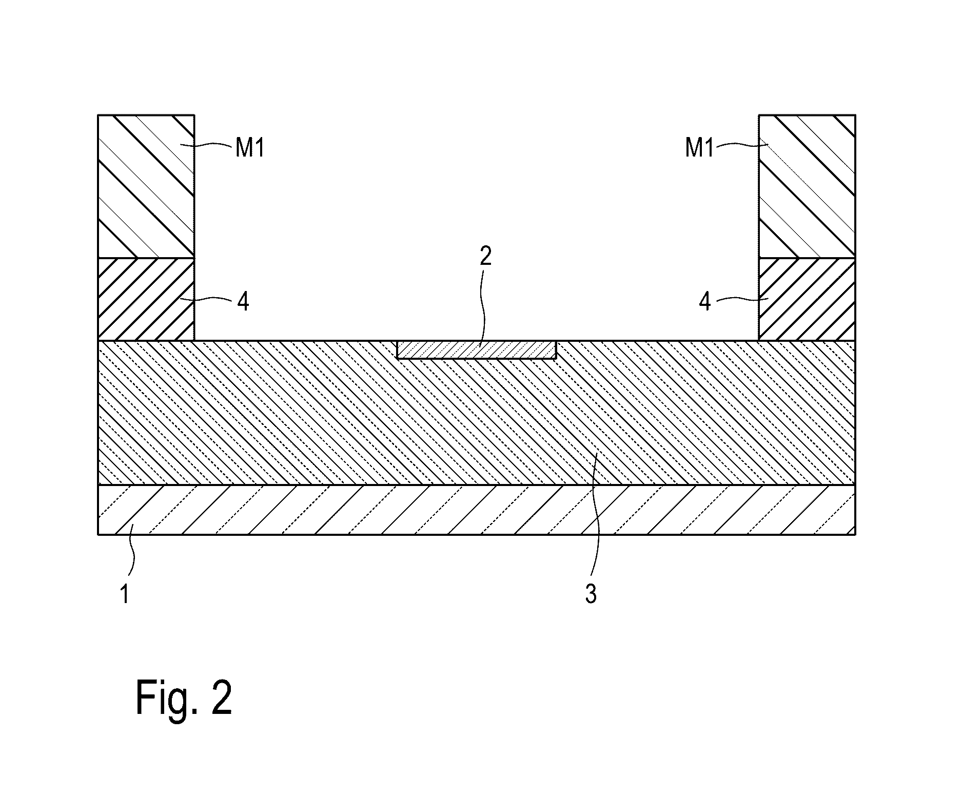
[0062]FIG. 12 shows the state of the region, in which the germanium PIN diode is subsequently produced, after production of a silicon waveguide 2 and subsequent etching of a window in an insulating layer 4 by means of a resist mask M1. Unlike the process for producing the first embodiment (see FIG. 2), waveguide 2 extends here laterally on both sides beyond the window etched in layer 4.

[0063]FIG. 13 shows the stage in the diode production process after subsequent selective, epitaxial growth of an undoped germanium layer 5 on silicon waveguide 2. In contrast to the production process for the first embodiment (see FIG. 3), a germanium layer thickness is chosen that is significantly greater than the thickness of insulator layer 4. The aim is to avoid facet formation underneath the top edge of layer 4.

[0064]FIG. 14 shows the diode structure after a Ge-CMP step which follows germa...


PUM


Abstract

A diode is described which comprises a light-sensitive germanium region (5) located on a waveguide (2) made of silicon or silicon germanium and which has lateral dimensions in a direction transverse to a direction of light propagation in the waveguide that are identical or at most 20 nm per side shorter in comparison with the waveguide.

Description

CROSS REFERENCE TO RELATED APPLICATIONS[0001]This application claims priority under 35 USC §119 to German Patent Application No. 102015207618.0 filed on Apr. 24, 2015 and German Patent Application No. 102015212208.5 filed on Jun. 30, 2015. Both applications are hereby incorporated by reference in their entirety.TECHNICAL FIELD[0002]The invention relates to a diode comprising a light-sensitive germanium region.BACKGROUND OF THE INVENTION[0003]Optical and optoelectronic components produced with a silicon-based technology are key components, for example for optical telecommunications or for optical connections within or between microelectronics circuits. Examples of such components are couplers, waveguides, modulators and photodetectors, in particular.[0004]Modern photodetectors use germanium (Ge) as a detector material due to its significantly better absorbance compared to silicon in the wavelength range used for optical communication (λ=1.3-1.6 μm). A PIN diode, so called, is often u...

Claims


Application Information

Patent Timeline
IPC IPC(8): H01L31/105H01L31/0232H01L31/02H01L31/0288
CPCH01L31/105H01L31/02005H01L31/02327H01L31/0288H01L31/022408G02B6/12004G02B6/42
Inventor KNOLL, DIETERLISCHKE, STEFAN
Owner IHP GMBH INNOVATIONS FOR HIGH PERFORMANCE MICROELECTRONICS LEIBNIZ INST FUR INNOVATIVE
Why Eureka
Try Eureka