Pellicle for EUV lithography

a pellicle and euv technology, applied in the field of pellicle for euv lithography, can solve the problems of difficult to make an adequate microscopic support structure, easy torn pellicle, and light becoming non-uniform, so as to reduce the brittleness increase the coupling strength of the inorganic layer and the strength reinforcing layer, and improve the strength of the pellicle film

Active Publication Date: 2017-02-09
IUCF HYU (IND UNIV COOP FOUND HANYANG UNIV)
View PDF0 Cites 18 Cited by
  • Summary
  • Abstract
  • Description
  • Claims
  • Application Information

AI Technical Summary

Benefits of technology

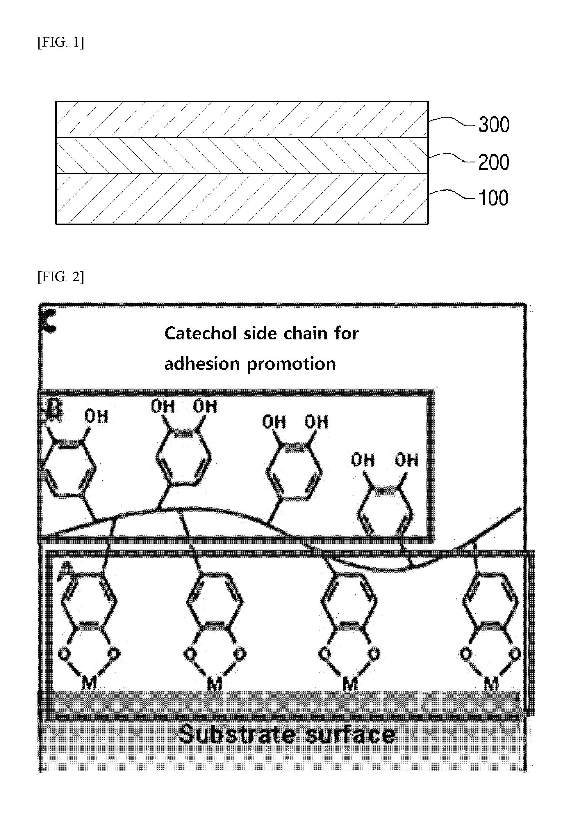
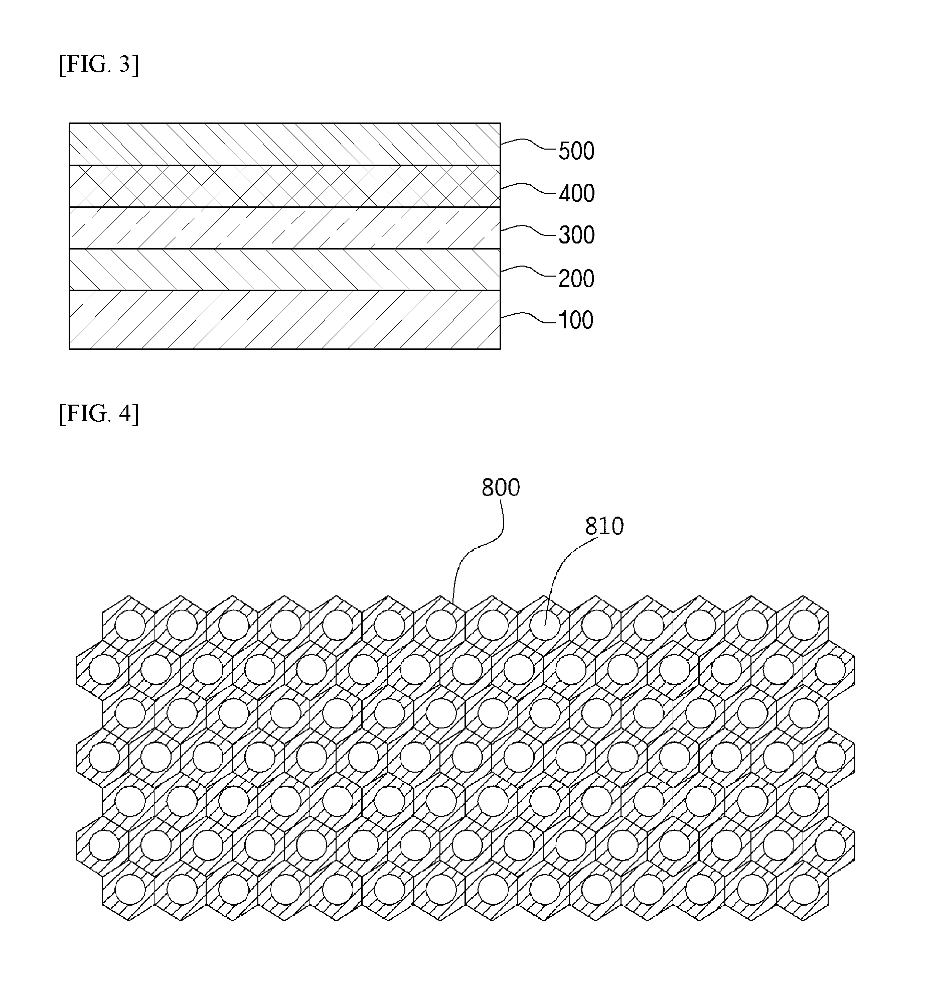
[0039]According to the present invention, strength of a pellicle film may be increased by having a strength reinforcing layer including a carbon nanostructure.
[0040]Also, by inserting a coupling layer including an organic material between an inorganic layer and a strength reinforcing layer, coupling strength between the inorganic layer and the strength reinforcing layer may be increased, and, further, brittleness of the inorganic layer can be alleviated using ductility of the organic material.
[0041]Also, because a separate support structure is not needed for reinforcing strength, there is no drawback of non-uniform EUV intensity due to the added support structure, after transmission through a pellicle.
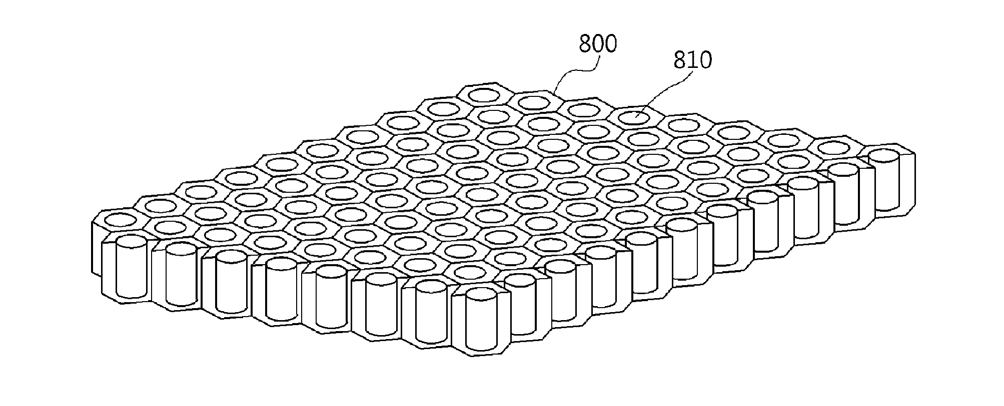
[0042]Also, according to another embodiment of the present invention, by using a porous thin film with a plurality of holes as the pellicle itself, increased strength may be achieved because thickness may be increased with still having EUV transmission that is higher compared to a single thin film pellicle without holes.
[0043]Also, a method of fabricating a pellicle for EUV lithography according to the present invention uses reproduction of a porous structure, and, by modifying a material deposited on a template for a pellicle, pellicle fabrication with a variety of materials is possible. Also, with such a pellicle material, selecting a material is possible for the purpose of adjusting strength and light transmission of a pellicle.
[0045]Also, because porous thin film pellicles can simply be repeatedly reproduced as long as there is a porous structure, for example, an AAO structure, a support layer fabrication method involving an inconvenient conventional patterning technique and etching technique can be substituted.

Problems solved by technology

While a pellicle made of a single thin film layer of silicon, that is, a pellicle for EUV lithography for which research has advanced the most may achieve adequate EUV transmission because a thin film is formed of mechanically weak silicon that is 100 nm or less, due to the low strength, fragility is a problem in which the pellicle is easily torn due to even a small impact, etc.
Further, there has been a problem in which it is extremely difficult to make an adequately microscopic support structure that can solve the problem of intensity EUV light becoming non-uniform.
On the other hand, when unwanted particles become attached on a lithography mask surface during an EUV exposure, defects due to the particles are formed during pattern formation using lithography.
Accordingly, such a pellicle causes loss of light.
Because such a pellicle made of a single thin film layer of silicon is just a single thin film layer of mechanically weak silicon that is 100 nm or less, adequate transmission of EUV is achieved, however fragility is a problem due to the low strength, where the pellicle is easily torn due to even a small impact, etc.
Further, there has been a problem in which it is extremely difficult to make an adequately microscopic support structure that can solve the problem of intensity of EUV light becoming non-uniform.

Method used


Image

  • Pellicle for EUV lithography
  • Pellicle for EUV lithography
  • Pellicle for EUV lithography

Examples


Embodiment Construction

[0056]Exemplary embodiments of the present invention are described in detail as follows, with reference to accompanying drawings.

[0057]While the present invention allows various modifications and transformations, specific embodiments are exemplified by the drawings and will be explained below in detail. However, there is no intent to limit the present invention to the specific form disclosed herein, and the present invention instead includes all modifications, equivalents, and alternatives included in the concepts and technical scope defined by the claims.

[0058]When it is mentioned that an element, such as a layer, an area, or a substrate exists “on” another element, it is to be understood that the element may exist directly on the other element or an intervening element may also exist therebetween.

[0059]Although words including “first”, “second”, etc. may be used to describe various elements, substances, areas, layers, and / or locations, these words are understood not to limit the e...


PUM

PropertyMeasurementUnit
thicknessaaaaaaaaaa
diameteraaaaaaaaaa
wavelengthaaaaaaaaaa

Abstract

A pellicle for EUV lithography is provided. The pellicle for EUV lithography may improve strength of a pellicle film by having a strength reinforcing layer including a first coupling layer and a carbon nanostructure disposed on a first inorganic layer, the first coupling layer here increase coupling strength between the first inorganic layer and the strength reinforcing layer, and a strength reinforcing layer including a carbon nanostructure. Also, a pellicle for EUV lithography according to another embodiment and a method of fabricating the same are provided. The pellicle for EUV lithography includes a plurality of holes and is a porous thin film made of a material with an extinction coefficient less than or equal to 0.02, and a diameter of the holes is less than or equal to 1 μm. Accordingly, improved strength is achievable because thickness may be made large with still having high EUV transmission.

Description

TECHNICAL FIELD[0001]The present invention relates to a pellicle for EUV lithography and, more particularly, a pellicle for EUV lithography with improved strength without a separate support structure and a pellicle for EUV lithography with increased EUV transmission and strength.BACKGROUND ART[0002]Extreme ultraviolet (EUV) lithography technology is a pattern forming technology using a 13.5 nm wavelength light source, which is very short compared to the conventional photolithography technology using 193 nm light from an ArF light source.[0003]This is considered a core technology for fabricating semiconductor devices having a line width of pattern with 22 nm or less.[0004]The EUV light source is strongly absorbed by all materials naturally in existence, and, therefore, design of necessary equipment for processing in terms of form, structure etc. changes from the conventional photolithography.[0005]Because EUV is so highly absorbed, for photolithography equipment, transmission optics ...

Claims


Application Information

Patent Timeline
Patent Type & Authority Applications(United States)
IPC IPC(8): G03F1/62G03F7/20
CPCG03F7/2004G03F1/62H01L21/027
Inventor AHN, JINHOLEE, JAEUKHONG, SEONGCHULLEE, SEUNGMINLEE, KILBOCKKIM, JUNGSIKKIM, JUNGHWAN
Owner IUCF HYU (IND UNIV COOP FOUND HANYANG UNIV)
Why Eureka
Try Eureka