Liquefied gas treatment system

a technology of liquefied gas treatment and treatment system, which is applied in the direction of liquefaction, lighting and heating apparatus, container discharge methods, etc., can solve the problems that the temperature and pressure of liquefied gas required by a source of demand, such as an engine, may be different, so as to improve the efficiency of re-liquefaction of boil-off gas for re-liquefaction, prevent waste of boil-off gas, and save fuel

Inactive Publication Date: 2017-04-27
HYUNDAI HEAVY IND CO LTD
View PDF8 Cites 14 Cited by
  • Summary
  • Abstract
  • Description
  • Claims
  • Application Information

AI Technical Summary

Benefits of technology

[0022]In the liquefied gas treatment system according to the present invention, boil-off gas is pressurized to be supplied to a source of demand, and a portion of the boil-off gas is expanded or decompressed to be re-liquefied. In this case, boil-off gas for re-liquefaction is heat-exchanged with the boil-off gas. Accordingly, the re-liquefaction efficiency of the boil-off gas for re-liquefaction can be improved by cold heat of boil-off gas, and waste of the boil-off gas can be prevented, thereby saving fuel.
[0023]Also, in the liquefied gas treatment system according to the present invention, when mass flow of boil-off gas for driving a boil-off gas compressor is insufficient, at least a portion of flash gas generated in a re-liquefaction process of the boil-off gas is joined with the boil-off gas, and the nitrogen control unit controls a ratio of nitrogen contained in the flash gas to be equal to or smaller than a set value a predetermined mass flow is supplied to boil-off gas compressor, so that recycle control can be minimized, thereby improving driving efficiency. In addition, the ratio of nitrogen in the system can be properly controlled. Accordingly, the efficiency of the boil-off gas compressor can be improved, and the system can be stabilized.
[0024]Also, in the liquefied gas treatment system according to the present invention, when a ratio of nitrogen contained in flash gas is equal to or greater than a set value, the nitrogen control unit controls at least a portion of the flash gas to be supplied to the liquefied gas storage tank so as to maintain the ratio of the nitrogen to be equal to or smaller than the set value, so that the flash gas can be stored and treated in the liquefied gas storage tank. Accordingly, environmental pollution due to discharging of the flash gas to the air can be prevented, and boil-off gas can be well supplied by increasing internal pressure of the liquefied gas storage tank.
[0025]Also, in the liquefied gas treatment system according to the present invention, when mass flow of boil-off gas for driving a boil-off gas compressor is insufficient, at least a portion of flash gas generated in a re-liquefaction process of the boil-off gas is joined with the boil-off gas. When a ratio of nitrogen contained in the flash gas is equal to or greater than a set value, the nitrogen control unit controls at least a portion of the flash gas to be supplied to the source of consumption so as to maintain the ratio of the nitrogen to be equal to or smaller than the set value. In this case, the flash gas is heat-exchanged with boil-off gas for re-liquefaction by the flash gas heat exchanger, so that the re-liquefaction efficiency of the boil-off gas for re-liquefaction can be improved. In addition, the flash gas can be treated in the source of demand, and thus environmental pollution due to discharging of the flash gas to the air can be prevented.
[0026]Also, in the liquefied gas treatment system according to the present invention, when mass flow of boil-off gas for driving a boil-off gas compressor is insufficient, at least a portion of flash gas generated in a re-liquefaction process of the boil-off gas is joined with the boil-off gas. When a ratio of nitrogen contained in the flash gas is equal to or greater than a set value, the nitrogen control unit controls at least a portion of the flash gas to be supplied to the gas combustion unit so as to maintain the ratio of the nitrogen to be equal to or smaller than the set value. In this case, the flash gas is heated by a heater, and waste heat generated from the gas combustion unit using a heat source of the heater is utilized, so that the combustion efficiency of the flash gas and the energy efficiency due to the use of waste heat can be improved. In addition, the flash gas can be treated in the gas combustion unit, and thus environmental pollution due to discharging of the flash gas to the air can be prevented.
[0027]Also, in the liquefied gas treatment system according to the present invention, a content of nitrogen is detected based on a change in pressure through the measurement of an internal pressure of the vapor-liquid separator, and nitrogen is discharged based on the detected content of the nitrogen, so that accumulation of the nitrogen in the system can be prevented. Accordingly, re-liquefaction efficiency can be improved, and driving power of the boil-off gas compressor can be optimized.

Problems solved by technology

However, the temperature and pressure of liquefied gas required by a source of demand, such as an engine, may be different from a state of liquefied gas stored in a liquefied gas storage tank.

Method used


Image

  • Liquefied gas treatment system
  • Liquefied gas treatment system
  • Liquefied gas treatment system

Examples


first embodiment

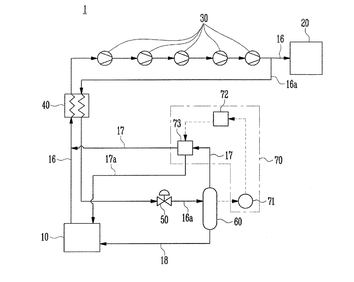
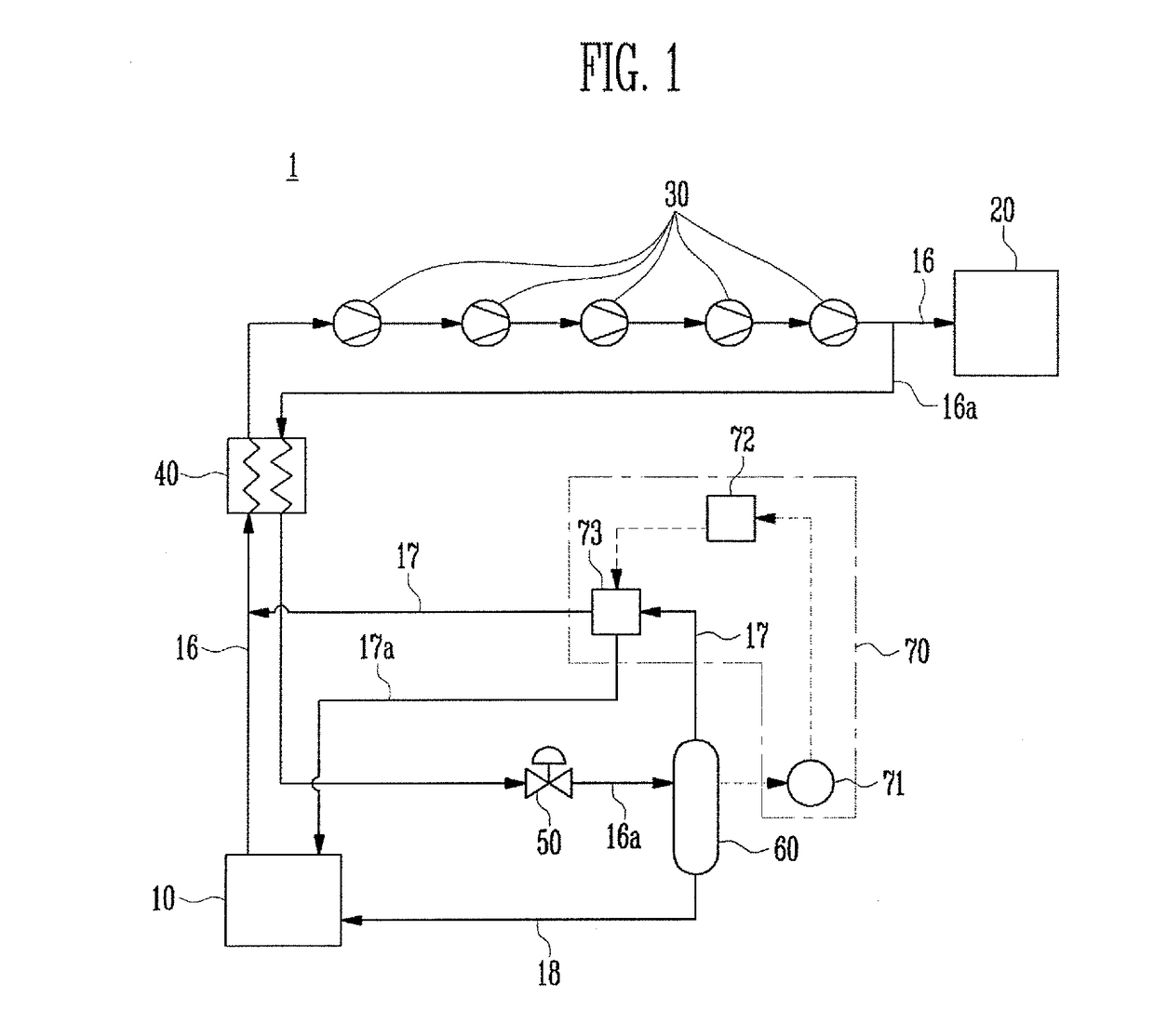
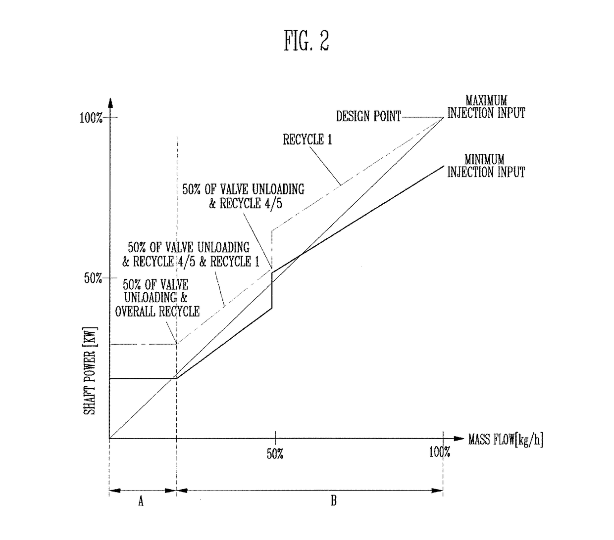
[0037]FIG. 1 is a conceptual diagram of a liquefied gas treatment system according to the present invention. FIG. 2 is a graph illustrating power consumption with respect to mass flow of a boil-off gas compressor in a general liquefied gas treatment system.

[0038]As shown in FIG. 1, the liquefied gas treatment system 1 according to the first embodiment of the present invention includes a liquefied gas storage tank 10, a source 20 of demand, a boil-off gas compressor 30, a boil-off heat exchanger 40, a boil-off liquefier 50, a vapor-liquid separator 60, and a nitrogen control unit 70.

[0039]Throughout the specification, liquefied gas may cover all types of gas fuels generally stored in liquid state, such as LNG or LPG, ethylene, and ammonia. For convenience, gas fuel which is not in liquid state as a result of heating or pressurization may also be expressed as liquefied gas. This is identically applicable to boil-off gas. In addition, LNG may refer to natural gas (NG) in both liquid st...

second embodiment

[0096]FIG. 3 is a conceptual diagram of a liquefied gas treatment system according to the present invention.

[0097]As shown in FIG. 3, the liquefied gas treatment system 2 according to the second embodiment of the present invention includes a liquefied gas storage tank 10, a source 20 of demand, a boil-off gas compressor 30, a boil-off gas heat exchanger 40, a boil-off gas liquefier 50, a vapor-liquid separator 60, a nitrogen control unit 70, a source 410 of consumption, and a flash gas heat exchanger 420. In comparison to the first embodiment of the present invention, the second embodiment of the present invention has a different configuration of the source 410 of consumption and the flash gas heat exchanger 420, and the connection relationship of a vapor treatment line 17a related to this configuration is different. For convenience, components identical or corresponding to those of the first embodiment of the present invention are designated by like reference numerals, and their ov...

third embodiment

[0109]FIG. 4 is a conceptual diagram of a liquefied gas treatment system according to the present invention.

[0110]As shown in FIG. 4, the liquefied gas treatment system 3 according to the third embodiment of the present invention includes a liquefied gas storage tank 10, a source 20 of demand, a boil-off gas compressor 30, a boil-off gas heat exchanger 40, a boil-off gas liquefier 50, a vapor-liquid separator 60, a nitrogen control unit 70, a gas combustion unit 510, and flash gas heaters 520a and 520b. In comparison to the first embodiment of the present invention, the first embodiment of the present invention has a different configuration of the gas combustion unit 510 and the flash gas heaters 520a and 520b, and the connection relationship of a vapor treatment line 17a related to this configuration is different. For convenience, components identical or corresponding to those of the first embodiment of the present invention are designated by like reference numerals, and their over...


PUM


Abstract

The present invention relates to a liquefied gas treatment system in which a nitrogen control unit controls a content of nitrogen in a boil-off gas or a flash gas when a ratio of a nitrogen component of the flash gas is equal to or greater than a preset value. The efficiency of a boil-off gas compressor can be improved and the system can be stabilized by means of the nitrogen control unit.

Description

TECHNICAL FIELD[0001]The present invention relates a liquefied gas treatment system.BACKGROUND ART[0002]With recent technological advances, liquefied gas, such as liquefied natural gas or liquefied petroleum gas, which replaces gasoline or diesel, has recently been widely used.[0003]Liquefied natural gas is gas that is converted into liquid form by cooling methane obtained by refining natural gas extracted from the gas field. The liquefied natural gas is a colorless, transparent liquid, and is a very excellent fuel that produces little pollution and has a high calorific value. On the other hand, liquefied petroleum gas is a fuel made by compressing gas, which is mainly composed of propane (C3H8) and butane (C4H10), extracted along with petroleum from oilfields, into liquid form at room temperature. Like the liquefied natural gas, the liquefied petroleum gas is colorless and odorless and has been widely used as household, commercial, industrial and automobile fuel.[0004]The above-des...

Claims


Application Information

Patent Timeline
Patent Type & Authority Applications(United States)
IPC IPC(8): F17C13/02F25J1/00
CPCF17C13/02F25J2240/40F17C2227/0157F17C2250/0636F17C2265/034F17C2223/0161F17C2223/033F17C2221/033F17C2265/01F17C2265/03F17C2265/033F17C2265/037F25J2205/02F25J2290/62F25J1/0025F25J1/004F25J1/0202F25J1/023F25J1/0244F25J2220/62Y02T10/12
Inventor LEE, JIN KWANGLEE, SANG BONG
Owner HYUNDAI HEAVY IND CO LTD
Why Eureka
Try Eureka