
Baffles, suppressors, and powder forming methods

a technology of suppressors and powder forming methods, which is applied in the direction of weapons, weapon components, etc., can solve the problems of inefficient use of materials, added time and cost to the forming process, and material cost disadvantages of both methods, so as to improve specific performance characteristics, high ductility, and reduce the effect of material cos

Active Publication Date: 2017-06-08
PRAXIS POWDER TECH
View PDF10 Cites 15 Cited by
  • Summary
  • Abstract
  • Description
  • Claims
  • Application Information

AI Technical Summary

Benefits of technology

The present invention is about improving high temperature performance by manipulating the chemistry of an alloy through the addition of oxygen or silicon. This can be done by altering the alloy's microstructure through the addition of very small amounts of these elements during powder forming. The resulting material is stronger at high temperatures and has improved mechanical performance. The invention also addresses the issue of wear resistance in the baffle material to improve the suppressor's lifespan by reducing the erosion of the bore edges caused by repeated firing.

Problems solved by technology

Although well received, both methods have disadvantages from a materials cost perspective.
This adds time and cost to the forming process.
Casting a near-net article and then machining it is more efficient than machining alone, but still has an inefficient use of material when the material wasted in the central sprue and the feed sprues is considered.
Further, casting often introduces voids into the material that can cause problems in subsequent operations such as machining or welding.
For example, alloys subjected to a conventional solution-treat-age cycle will have an improved microstructure (and improved mechanical performance) at room temperature, but heating the material will alter the microstructure and diminish the high temperature properties.

Method used


Image

  • Baffles, suppressors, and powder forming methods
  • Baffles, suppressors, and powder forming methods
  • Baffles, suppressors, and powder forming methods

Examples


Embodiment Construction

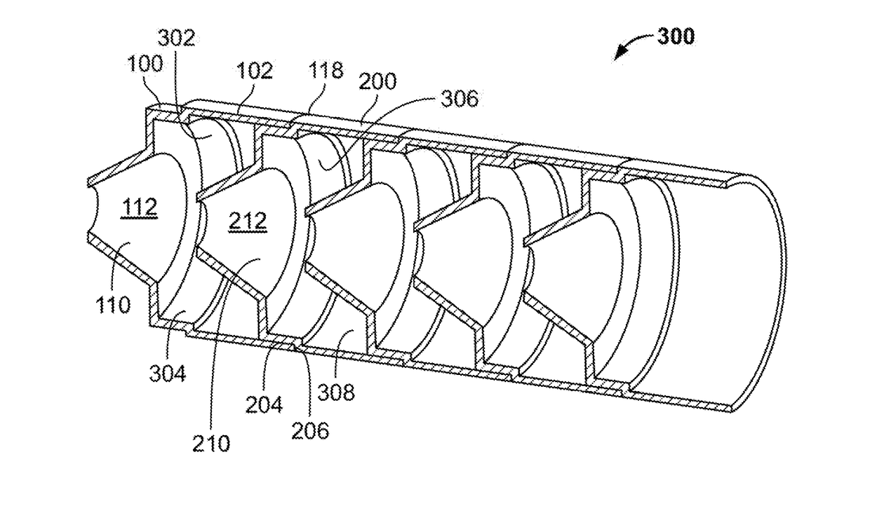
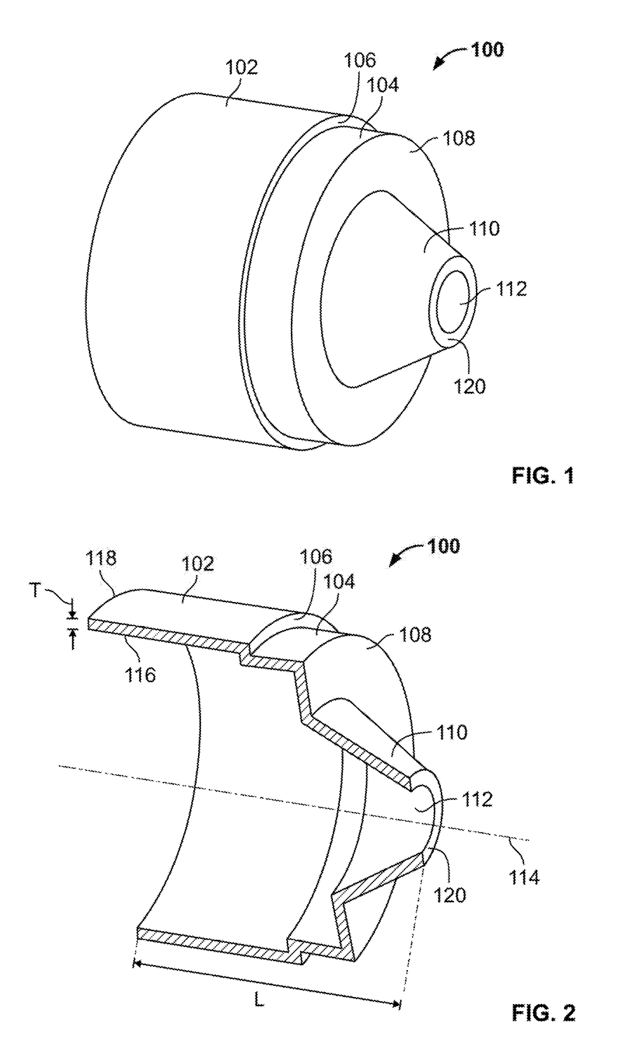
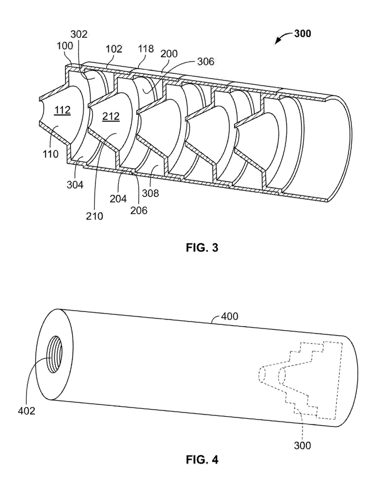
[0054]In the following are described the preferred embodiments of the BAFFLES, SUPPRESSORS, AND POWDER FORMING METHODS in accordance with the present invention. In describing the embodiments illustrated in the drawings, specific terminology will be used for the sake of clarity. However, the invention is not intended to be limited to the specific terms so selected, and it is to be understood that each specific term includes all technical equivalents that operate in a similar manner to accomplish a similar purpose. Where like elements have been depicted in multiple embodiments, identical reference numerals have been used in the multiple embodiments for ease of understanding.

[0055]Rather than utilizing the conventional methods of (i) machining or (ii) casting followed by machining, it has been found that powder forming presents efficient routes for manufacturing thin-walled cone geometries such as suppressor baffles. These net-shape or near net-shape forming routes can substantially re...


PUM

PropertyMeasurementUnit
Fractionaaaaaaaaaa
Fractionaaaaaaaaaa
Fractionaaaaaaaaaa

Abstract

A method of forming a firearm suppressor baffle including preparing a titanium alloy powder system, forming of the powder system into a green shape, optionally green machining the green shape, sintering the green shape to create a firearm suppressor baffle formed from sintered material, where the firearm suppressor baffle has an elevated oxygen content of between 0.2 and 0.5 weight percent. The resultant sintered material may have a creep value of less than 1.5% at 50 hours at 450 C. Also, a method of forming a firearm suppressor baffle including preparing a titanium aluminide powder system, forming the titanium aluminide powder system into a green shape through one of compaction and powder metal injection molding, and sintering the green shape to create the firearm suppressor baffle. The titanium aluminide powder method may also include deoxygenating the firearm suppressor baffle. Also disclosed are baffles and suppressors formed using these methods.

Description

CROSS-REFERENCE TO RELATED APPLICATIONS[0001]The present application claims benefit of U.S. Provisional Patent Application Ser. No. 62 / 264,225, filed Dec. 7, 2015, and entitled “SUPPRESSOR AND POWDER FORMING METHODS FOR MANUFACTURING,” the disclosure of which is hereby incorporated by reference herein.BACKGROUND OF THE INVENTION[0002]Suppressors or silencers (referred to herein as “suppressors”) are used to reduce the amount of noise and / or muzzle flash emitted from a firearm upon firing. Typically, suppressors are constructed with an array or stack of cone shaped thin-walled baffles. This assembly creates a complicated pathway designed to redirect and slow explosive gases escaping from the barrel of the firearm while the projectile travels through freely.[0003]Because the suppressor baffles are stacked together they generally require high precision with respect to their mating surfaces. Further, they need to be constructed of material that can withstand the heat and pressure that t...

Claims


Application Information

Patent Timeline
IPC IPC(8): F41A21/30B22F3/16C22C14/00B22F3/00B22F5/10B22F1/00B22F3/15
CPCF41A21/30B22F1/0003B22F3/162B22F3/15B22F3/004B22F2303/01C22C14/00B22F2301/205B22F2302/253B22F2302/45B22F2998/10B22F5/106C22C1/0458C22C33/0285B22F2207/20B22F3/02B22F3/225
Inventor PIEMME, JOBEGROHOWSKI, JR., JOSEPH A.SHEFFIELD, PAUL H.
Owner PRAXIS POWDER TECH
Learn More