
Stationary real time ct imaging system and method thereof

a real-time ct imaging and imaging system technology, applied in the field can solve the problems of long scan time, poor reconstruction image quality, low utilization rate of ct imaging systems, etc., and achieve low dose high performance imaging, reduced scattering interference, and high signal-to-noise ratio

Active Publication Date: 2017-06-15
NANOVISION TECHNOLOGY (BEIJING) CO LTD
View PDF5 Cites 20 Cited by
  • Summary
  • Abstract
  • Description
  • Claims
  • Application Information

AI Technical Summary

Benefits of technology

The present invention is a new technology that uses a faster and more accurate way to acquire image data. Stabilization of the acquisition mode allows for faster scanning and reduced motion trails, overlapping, and crosstalk. The technology also allows for divided area imaging and increased accuracy and speed in diagnosing patients with safer doses. Additionally, the technology reduces scattering interference and provides low dose high performance imaging solutions with high signal to noise ratios in lower doses.

Problems solved by technology

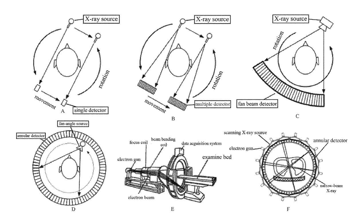
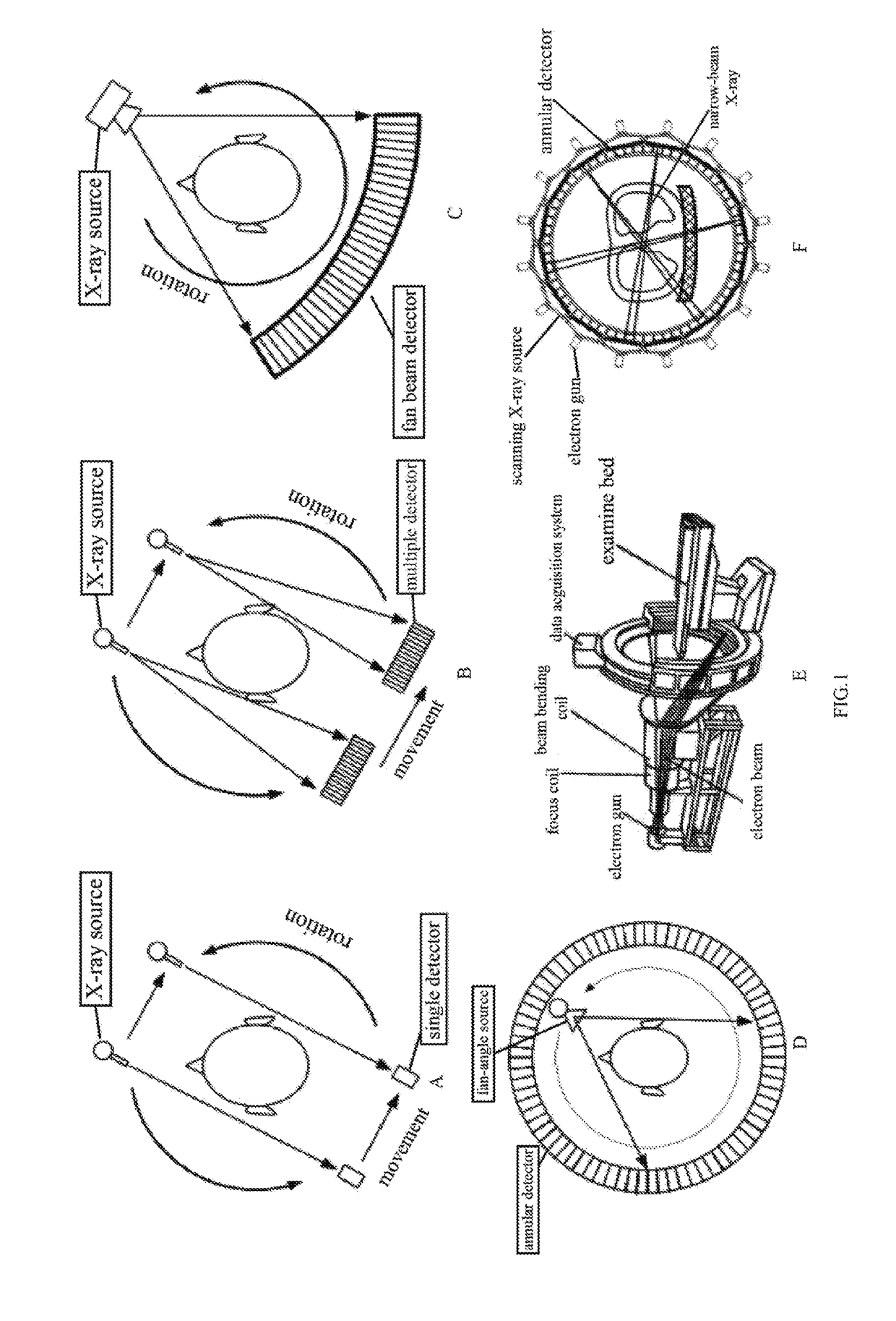
However, such a CT imaging system has low utilization of x-ray, long scan time, poor reconstruction image quality.
However, cone-beam CT imaging system has serious imaging scattering.
Therefore, smaller pixels hardly bring fan-beam CT imaging system the same signal to noise ratio, which is the main bottleneck to improve image quality.
However, the existing CT imaging system for imaging still fast enough, there are motion artifacts and other issues.
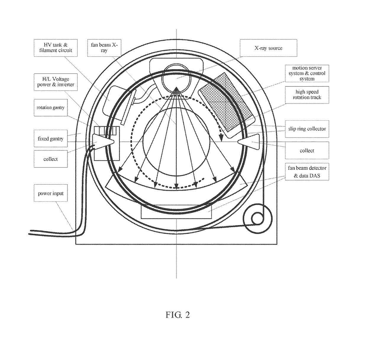
Unfortunately, x-ray sources and x-ray detectors set at high speed rotating frame rotating 2 circles per second or even faster, cause x-ray source, high voltage generators and other assembles to work under the centrifugal force, therefore it turns to be a manufacturing technology bottleneck.
Because detector pixels signals are integration of the electric signals during a slight displacement, the spatial resolution encounters a bottleneck in a state of high speed rotation, and becomes conflict with rotation speed.
Thus, signals at different locations crosstalk and overlap (that is, motion trail) more severely.
The other hand, the detector has more and more layers, x-ray beams from a x-ray source are wider and wider, x-ray scattering is more and more serious, resulting in the CT images become blurred.
This kind of x-ray detectors cannot distinguish between each x photon spectrum, thus losing energy spectrum information.

Method used


Image

  • Stationary real time ct imaging system and method thereof
  • Stationary real time ct imaging system and method thereof
  • Stationary real time ct imaging system and method thereof

Examples


Embodiment Construction

[0059]The present invention is described in further detail below with reference to accompanying drawings and specific embodiments.

[0060]As shown in FIG. 4, the present invention provides stationary real-time CT imaging system which includes a parallel set of annular scanning x-ray sources (referred to annular x-ray source) and annular photon-counting detectors (referred to annular detector). The annular scanning x-ray source and the annular photon-counting detectors (further explained below) do not locate in the same plane, but in different planes parallel to each other. Their ring structures are concentric. In other words, the normals respectively penetrating the centers of their ring structures coincide with each other. This design can prevent the x-ray beams from the scanning x-ray source to the photon-counting detector from being interrupted by an overlapped structure, and can ensure narrow-beams x-ray from each x-ray source project onto a photon-counting detector module. To ens...


PUM


Abstract

The present invention discloses a stationary real-time CT imaging system, comprising an annular photon counting detector, an annular scanning x-ray source, and a scanning sequence controller. Under the control of the scanning sequence controller, the annular scanning x-ray source emits x-ray, and the x-ray penetrates the object being tested and projects onto the corresponding annular photon counting detector. The annular photon counting detector delivers the corresponding exposure information through the main scanning machine and the main controlling unit to a CT main machine and a human-machine interface unit. The image reconstruction is completed in the CT main machine and the human-machine interface unit. By electronically controlling and switching x-ray projection positions in order, the scanning speed is enhanced by tens of times, thereby obtaining dynamic 3D images. The use of the photon counting detector enables the access to absorption data and energy data, thereby allows for real-time data reconstruction.

Description

CROSS REFERENCE TO RELATED APPLICATION[0001]This application is a continuation of International Application No. PCT / CN2015 / 088067, filed on Aug. 25, 2015, which claims priority to Chinese patent application No. 201410425061.2, filed on Aug. 26, 2014, the content of which are incorporated herein by reference in their entirety.FIELD OF THE INVENTION[0002]The present invention relates to a CT imaging system, particularly to a stationary real time CT imaging system using an annular scanning x-ray source and an annular photon counting detector, and also relates to a real-time CT imaging method based on the CT imaging system, belonging to a field of medical imaging technology.BACKGROUND OF THE INVENTION[0003]CT (Computed Tomography) is the abbreviation of computer tomography technology. Its imaging principle is as follows: using x-ray beam and x-ray detector of high sensitivity, a part of one person is scanned around by serial slices tomography, the x-ray penetrating the slice of the pers...

Claims


Application Information

Patent Timeline
Patent Type & Authority Applications(United States)
IPC IPC(8): A61B6/03A61B6/00A61B6/04
CPCA61B6/032A61B6/0407A61B6/4275A61B6/4266A61B6/4007A61B6/4241A61B6/06A61B6/486A61B6/5282A61B6/03G01N23/04G01N23/046G01T1/29A61B6/4014G01N23/10H05G1/46H05G1/70
Inventor CAO, HONGGUANGLI, YUNXIANGCHANG, TONGCUI, ZHILIZHENG, HAILIANG
Owner NANOVISION TECHNOLOGY (BEIJING) CO LTD
Learn More