
Sensing System Based on a Fluorophore Array

a technology of fluorophore array and sensing system, which is applied in the direction of fluorescence/phosphorescence, optical detection, instruments, etc., can solve the problems of ignoring the detection of trace quantities of explosives in the gas phase, pushing the limits of most methods including modern fluorescent techniques, and unable to meet the challenge of detecting multiple analytes in their respective gas phase using strong fluorophore-based signals

Active Publication Date: 2017-08-10
BOARD OF GOVERNORS FOR HIGHER EDUCATION STATE OF RHODE ISLAND & PROVIDENCE PLANTATIONS
View PDF0 Cites 6 Cited by
  • Summary
  • Abstract
  • Description
  • Claims
  • Application Information

AI Technical Summary

Benefits of technology

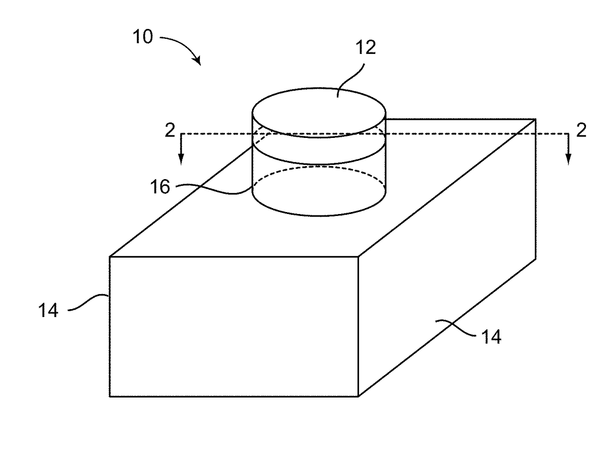
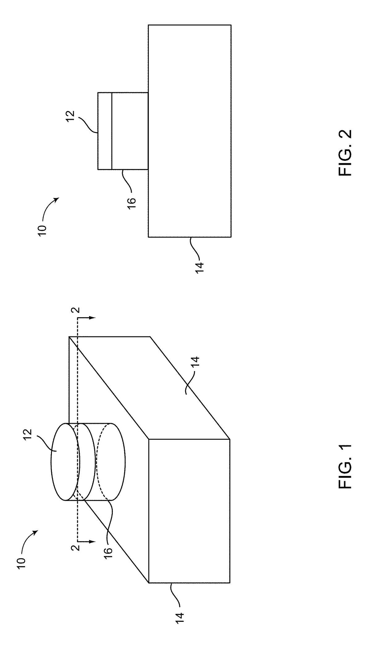
The present invention provides a sensing system that can detect a variety of explosive analytes and related materials using a three-layer structure with a support or substrate, a transparent layer, and on top discreet pixels or cells each containing at least one fluorophore. The system can detect optical responses from multiple combinations of fluorophore, polymer, and thickness of the polymer layer. The detected optical responses are compared to a signature pattern or profile of each target chemical to determine whether the analyte is one of the target chemicals. The invention also provides a method for detecting an explosive or related material using the sensing system. The technical effects of the invention include the ability to detect a variety of explosive analytes and related materials with high sensitivity and accuracy, even in their gas phase and at room temperature.

Problems solved by technology

However, detection of trace quantities of explosives in the gas phase has remained a significant challenge to analytical chemistry.
The low vapor pressure of most explosives, in the parts per billion (ppb) to parts per trillion (ppt) ranges at room temperature, pushes the limits for most methods including modern fluorescent techniques.
Further, the challenge of detecting multiple analytes in their respective gas phase using strong fluorophore-based signals remained unmet.

Method used


Image

  • Sensing System Based on a Fluorophore Array
  • Sensing System Based on a Fluorophore Array
  • Sensing System Based on a Fluorophore Array

Examples


examples

[0043]The xanthene dyes used in this example, rhodamine 6G (Rh6G), rhodamine 560 (Rh560), rhodamine 640 (Rh640), sulforhodamine B (SRhB), and fluorescein 548 (Fl548), were obtained from Exciton, Inc. and used without further purification. Ethanol (95%), acetone, tetrahydrofuran (THF), and dimethylformamide (DMF) were obtained from Sigma Aldrich or Fisher Scientific and used without further purification. The dyes were dissolved in 95% ethanol at a concentration of 1.0×10⁻⁴M for use in spin-coating. The polymers used, polymethylmethacrylate (MW 120,000, PMMA) and polyvinylidene difluoride (MW 534,000, PVDF), were obtained from Sigma Aldrich. PMMA was dissolved in toluene to form a 5% (w / v) solution. PVDF was dissolved in a solution of 9 / 1 (v / v) acetone / DMF at two concentrations, 2% (w / v) and 4% (w / v). Samples for spectroscopy were prepared by cleaning glass microscope slides in ethanol and then spin-coating the polymers onto the glass slide (acceleration of 1080 s−2 to 1200 rpm) under...


PUM

PropertyMeasurementUnit
thicknessaaaaaaaaaa
refractive indexaaaaaaaaaa
thickaaaaaaaaaa

Abstract

A sensing system for explosives is provided. The sensor is based on a layered structure of approximately a monolayer of a fluorophore deposited onto a few nm of a transparent polymer, supported by a substrate. The fluorophores can be xanthene laser dyes, which have high quantum yields, and the polymers can be commodity materials polymethylmethacrylate and polyvinylidene difluoride. The different fluorophore / polymer combinations give different emission responses to analytes, including both signal quenching and enhancement. The pattern of responses can be used to identify the analyte. The common explosives TNT, PETN, RDX, HMX, and TATP as gas phase species can all be uniquely identified at room temperature using only the natural vapor pressure of the explosive to deliver sample to the sensor.

Description

CROSS-REFERENCE TO RELATED APPLICATIONS[0001]This application claims priority to and the benefit of co-pending U.S. provisional patent application Ser. No. 62 / 293,696, filed on Feb. 10, 2016, which application is incorporated herein by reference in its entirety.STATEMENT REGARDING FEDERALLY SPONSORED RESEARCH OR DEVELOPMENT[0002]The invention described herein was made with government support under grant nos. 2008-ST-061-ED0002 and 2013-ST-061-ED0001, awarded by U.S. Department of Homeland Security. The government has certain rights in the invention.BACKGROUND OF THE INVENTION[0003]Major efforts have been undertaken in the world to develop, certify and deploy explosive detection systems. In recent years, at least 2000 to 3000 explosive incidents warranting investigation have occurred within the United States and a comparable number in other countries. As the spread of terrorism rose to an alarming proportion across the globe, the need for sensitive yet reliable detection of concealed...

Claims


Application Information

Patent Timeline
Patent Type & Authority Applications(United States)
IPC IPC(8): G01N33/22G01N21/64G01V8/20
CPCG01N33/227G01N2021/6432G01N21/643G01V8/20G01N33/0057
Inventor EULER, WILLIAM B.
Owner BOARD OF GOVERNORS FOR HIGHER EDUCATION STATE OF RHODE ISLAND & PROVIDENCE PLANTATIONS
Learn More