Micro single-fiber bidirectional optical transceiver module of the same wavelength

a bidirectional optical transceiver and micro single-fiber technology, applied in optics, instruments, diffraction gratings, etc., can solve the problems of inconformity of the propagation delay of the two signals, increase the inventory pressure, and huge difficulty in clock synchronization, etc., to achieve compact structure and low cost

Active Publication Date: 2017-08-24
XUZHOU XUHAI OPTO ELECTRONICS TECH CO LTD
View PDF4 Cites 16 Cited by
  • Summary
  • Abstract
  • Description
  • Claims
  • Application Information

AI Technical Summary

Benefits of technology

The present invention provides a solution to meet the needs of integration and miniaturization of optical communication devices by using a single-fiber bidirectional optical transceiver module of the same wavelength. The use of multiple birefringent crystals or thin-film polarization beam splitters based solutions has limitations in terms of size and cost. However, the present invention uses a polarization reflector based on sub-wavelength grating structure, which simplifies the optical structure and reduces the cost. The sub-wavelength grating reflects light of one polarization state and transmits to another perpendicular polarization state, making it an essential feature in the present invention.

Problems solved by technology

The traditional optical transceiver module transmits and receives the optical signals by using two optical fibers, respectively, the length of the two optical fibers in the practical application will cause the propagation delay of the two signals inconformity, which causes huge difficulty to the clock synchronization.
This is not only increase the inventory pressure, but also increase a certain difficulty in field deployment.
Besides, due to the effect of the dispersion, the two different wavelengths also have a certain delay inequality even being transmitted in the same optical fiber, which can not meet the demand for high accuracy of clock synchronization in the application scenario.
The existing technology shown in FIG. 2 has a significant deficiency, that is the beam splitter (204) and (205) can produce a total of 6 dB link loss.
And in many applications, the extra 6 dB loss is unacceptable.
However, the technical solution adopts overmuch optical element, which increases the cost; and two polarization-state transmission paths have larger separation in space, which also causes the volume difficult to further reducing.
The above scheme still uses a plurality of optical elements, causing big volume and high cost, and assembly difficulty.
US Patent Application US20140054657, US20080042050 and the above U.S. Pat. No. 7,039,278B1 also revealed using a pair of birefringent crystals, inserting half wave plate and a Faraday rotator in the middle to separate the transmitting and receiving channels, however, the basic limitation is the distance of the transmitting and receiving channels is in direct proportion to the length of the birefringent crystals, to make the position of the transmitting and receiving channels having enough separation, the length of the optical element is close to 10 mm.
However, the scheme needs integrated transmitting and receiving chip, the process isn't easy to realize and the cost is high.
Besides, the transmitting and receiving chip are too close, the reflected light from the lens surface, which is originally emitted from the transmitting laser chip, can easily get into the optical detector; for the power of optical signal emitted from the transmitting laser chip is very high, so even a small reflection will produce unacceptable crosstalk to the receiving end.
In conclusion, the existing single-fiber bidirectional transmission solution with the same wavelength has the lack of performance, size, and cost more or less, therefore, a new technology of low cost without larger crosstalk and loss, and small sized single-fiber bidirectional optical transceiver module with the same wavelength is needed.
It can be seen that the use of a plurality of birefringent crystals or a plurality of multilayer thin-film polarization beam splitters based solution has the limitation of size and cost, which cannot be further reduced according to the analysis of above.

Method used


Image

  • Micro single-fiber bidirectional optical transceiver module of the same wavelength
  • Micro single-fiber bidirectional optical transceiver module of the same wavelength
  • Micro single-fiber bidirectional optical transceiver module of the same wavelength

Examples


embodiment 1

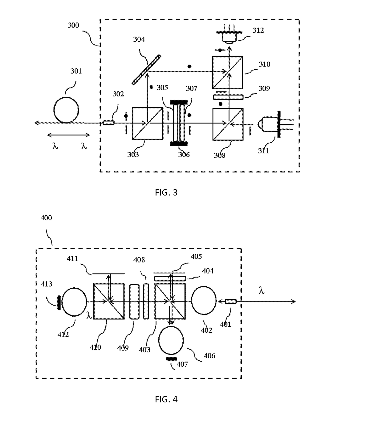
[0074]As shown in FIG. 14, one embodiment of the miniaturized single-fiber bidirectional optical transceiver module (1400) of the same wavelength provided by the present invention, comprising:

[0075]1. an input / output end (1401), configured to input and output an optical signal;

[0076]2. a sub-wavelength grating polarization beam splitter / combiner (1403);

[0077]3. a first polarization reflector (1404);

[0078]4. a second polarization reflector (1405);

[0079]5. an optical signal transmitting unit (1406);

[0080]6. an optical signal receiving unit (1407).

[0081]the input / output end (1401) receives an incident optical signal comprising one wave length, and inputs the received incident optical signal into the polarization beam splitter / combiner (1403) of sub-wavelength grating type; and disintegrated into the first and the second polarization-state optical signal that are perpendicular to each other, which are respectively transmitted along a transmission path and a reflection path to the first ...

embodiment 2

[0087]As shown in FIG. 15, one embodiment of the miniaturized single-fiber bidirectional optical transceiver module (1500) of the same wavelength provided by the present invention, comprising:

[0088]1. an input / output end (1501), configured to input and output an optical signal;

[0089]2. a collimating lens (1502);

[0090]3. a polarization beam splitter / combiner of a multi-layer dielectric thin film type (1503);

[0091]4. a first polarization reflector (1504);

[0092]5. a second polarization reflector (1505);

[0093]6. a first optical signal transmitting unit (1506) and a second optical signal transmitting unit (1510);

[0094]7. a first optical signal receiving unit (1507) and a second optical signal receiving unit (1513);

[0095]8. a wavelength filter of multi-layer dielectric thin film type (1514).

[0096]The input / output end (1501) receiving contains two incident optical signals of two wavelengths, the wavelengths are λ1 andλ2, and inputting the received incident optical signal to the polarizatio...

embodiment 3

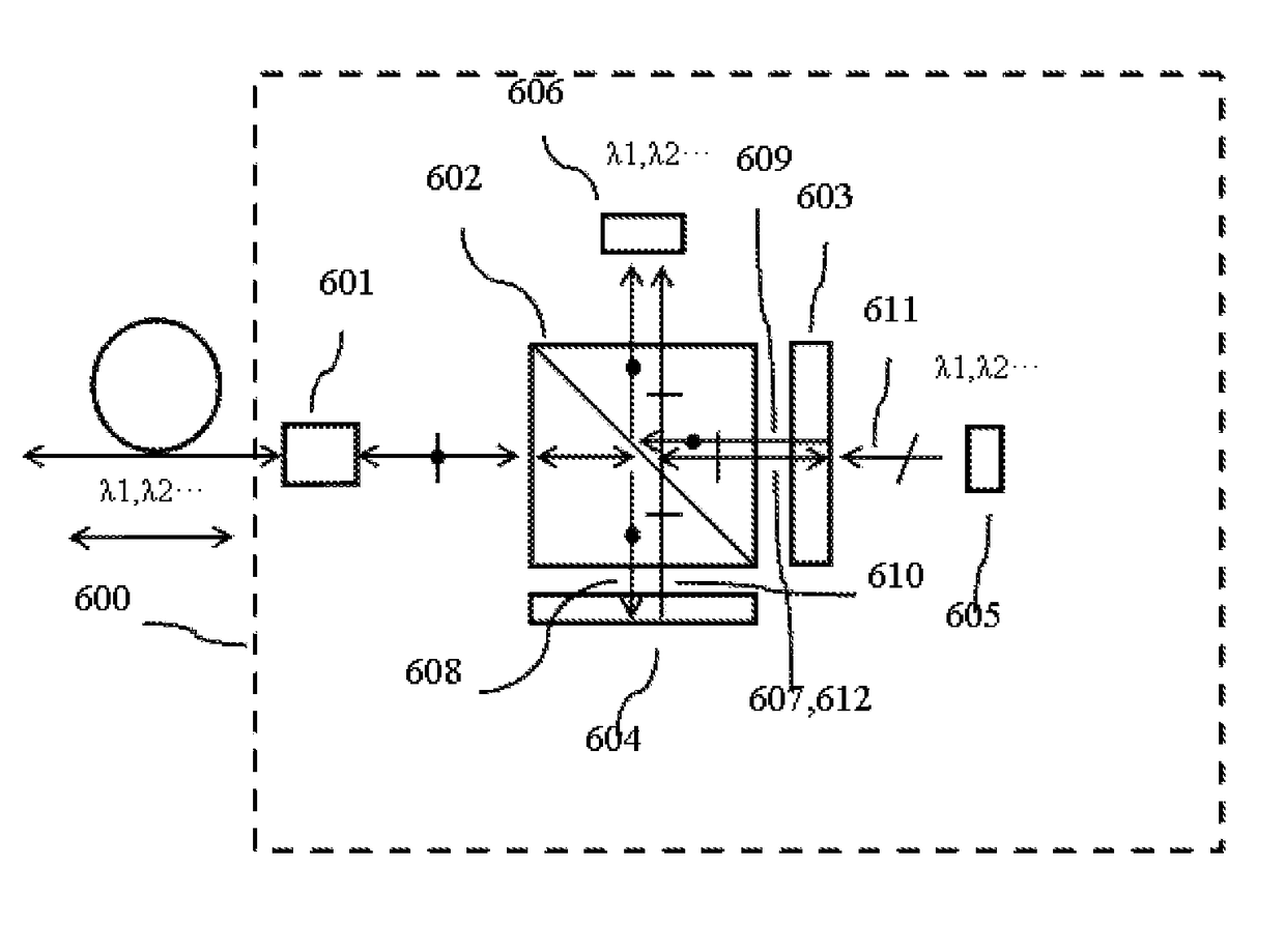
[0102]As shown in FIG. 16, one embodiment of the miniaturized single-fiber bidirectional optical transceiver module (1600) of the same wavelength provided by the present invention, comprising:

[0103]1. an input / output end (1601), configured to input and output an optical signal;

[0104]2. a wavelength multiplexer / de-multiplexer (1602);

[0105]3. a polarization beam splitter / combiner (1603);

[0106]4. a first polarization reflector;

[0107]5. a second polarization reflector;

[0108]6. an optical signal transmitting unit group (1606);

[0109]7. an optical signal receiving unit group (1607).

[0110]The input / output end (1601) receives the incident optical signal comprising multi wavelengths λ1, λ2 . . . λn and inputs to the wavelength multiplexer / de-multiplexer (1602), the incident optical signals with different wavelength are separated on the direction (1605) perpendicular to the plane (1604) that made of transmission and reflection path of the polarization beam splitter / combiner, which incidents on...


PUM

PropertyMeasurementUnit
sizeaaaaaaaaaa
refractive indexaaaaaaaaaa
lengthaaaaaaaaaa

Abstract

A single-fiber bidirectional optical transceiver module of the same wavelength. A sub-wavelength grating and a Faraday rotator are used, and the same element is reused to implement a polarization multiplex / de-multiplex function, so as to implement transmission and receiving of an optical signal in a small space. The single-fiber bidirectional optical transceiver module has less optical elements, a compact structure, and low cost, meeting the needs on a miniaturized, integrated, and high speed optical transceiver module for a modern optical communication system.

Description

[0001]This application is the U.S. national phase of International Application No. PCT / CN2015 / 076936 filed on 20 Apr. 2015 which designated the U.S. and claims priority to Chinese Application Nos. CN201410604190.8 on 27 Oct. 2014, the entire contents of each of which are hereby incorporated by reference.TECHNICAL FIELD[0002]The present invention relates to an optical transceiver module of using an optical fiber for bidirectional optical signal transmission, and more particularly to the use of same wavelength and wavelength group with no need for the optical transceiver module to be paired on wavelength for single-fiber bidirectional transmission, having the feature of structure miniaturization.BACKGROUND OF THE INVENTION[0003]High-speed data transmission is the foundation of modern information society, the requirement of the data capacity that transmits in a fiber gets bigger and bigger with the massive growth of the amount of information. In addition to increasing modulation rate a...

Claims


Application Information

Patent Timeline
Patent Type & Authority Applications(United States)
IPC IPC(8): G02B6/42G02B27/42G02B5/18G02B6/27G02F1/09
CPCG02B6/4213G02B6/2706G02B6/4246G02B27/4261G02B6/2766G02F1/09G02B5/1809G02B6/2773G02B6/00
Inventor CHEN, BOHE, GUANGZHIPANG, XIANGXIANG
Owner XUZHOU XUHAI OPTO ELECTRONICS TECH CO LTD
Why Eureka
Try Eureka