Electric power system and control method thereof

US20170250538A1Active Publication Date: 2017-08-31DELTA ELECTRONICS SHANGHAI CO LTD

Image

  • Electric power system and control method thereof
  • Electric power system and control method thereof
  • Electric power system and control method thereof

Examples


first embodiment

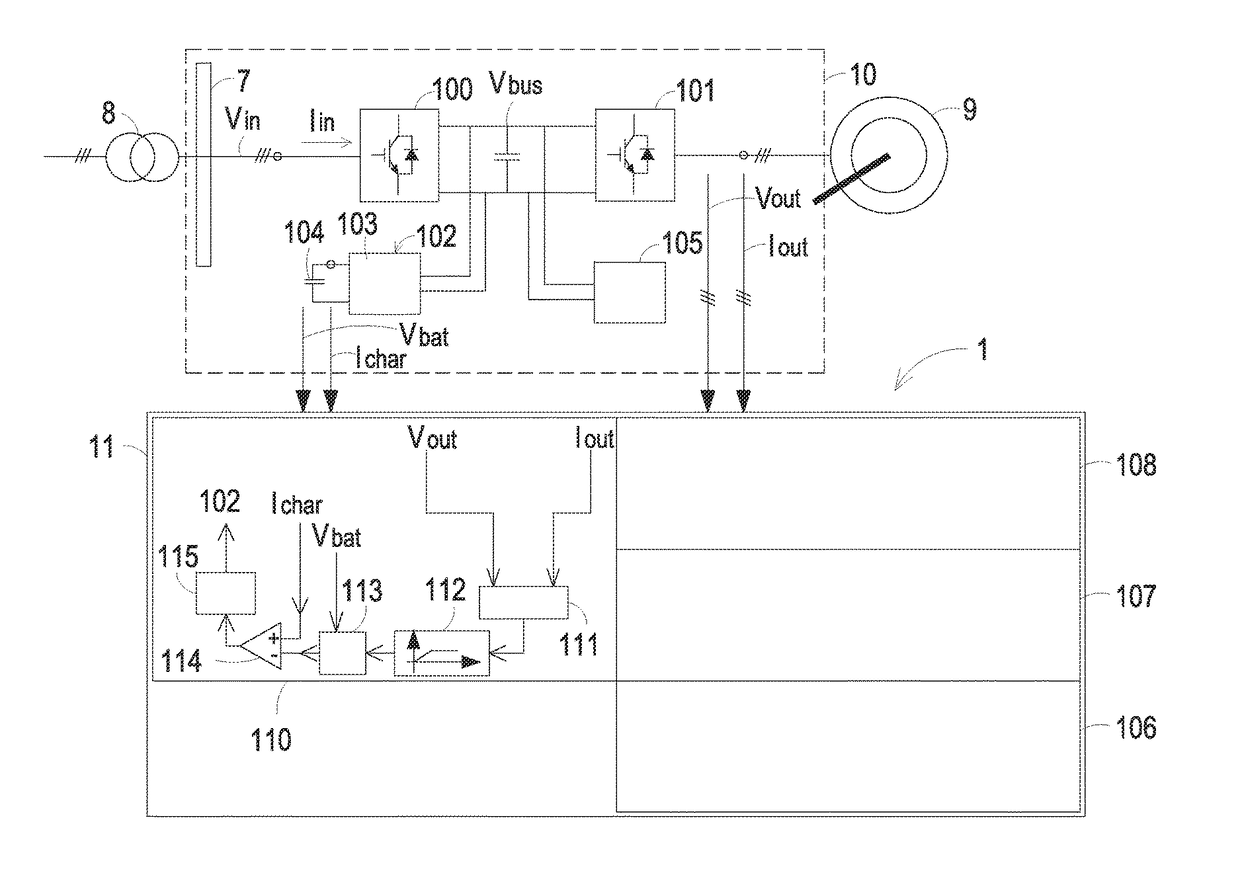
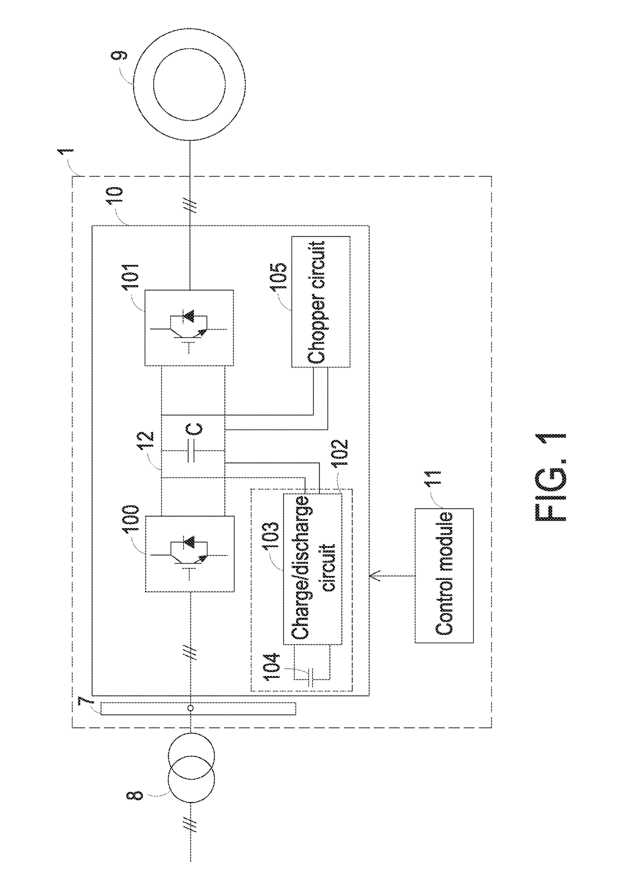
[0031]FIG. 1 is a schematic circuit block diagram illustrating an electric power system for a ship according to the present invention. The electric power system 1 is used for driving an inductive load in a ship. For example, the inductive load is an electric motor 9. As shown in FIG. 1, the electric power system 1 comprises a variable-frequency drive 10 and a control module 11. The variable-frequency drive 10 is connected between a power generator 8 and the electric motor 9. When the electric motor 9 is in an electric motor mode, the variable-frequency drive 10 receives a first power from the power generator 8 (i.e., an input power) and converts the input power into a second power. The second power is provided to the electric motor 9 in order to drive the operation of the electric motor 9. On the other hand, when the electric motor 9 is in a power generation mode, the variable-frequency drive 10 selectively converts the electric energy that is generated by the electric motor 9. The ...

fifth embodiment

[0061]FIG. 10 is a schematic circuit diagram illustrating an electric power system and a control module according to the present invention. Component parts and elements corresponding to those of FIG. 7 and FIG. 9 are designated by identical numeral references, and detailed descriptions thereof are omitted. As mentioned above, the electric power system 3 of FIG. 9 has a single energy storage module 102. Like the electric power system 2 of FIG. 7, the electric power system 4 of this embodiment comprises plural energy storage modules. The electric power system 4 comprises a first energy storage module 61 and a second energy storage module 62. In this embodiment, the energy storage controller 110 of the control module 11 comprises a spectral computing unit 601, a first high pass filter 602, a second high pass filter 603, a differential comparator 604, a first current computing unit 605, a second current computing unit 606, a first comparing unit 607, a second comparing unit 608, a first...


PUM


Abstract

An electric power system includes a variable-frequency drive and a control module. The variable-frequency drive includes a first power converter, a second power converter and at least one energy storage module. The first power converter is connected between a DC bus and a power terminal. Moreover, electric energy is transferred between the first power converter and the power terminal at a first power. The second power converter is connected between the DC bus and an electric / kinetic energy conversion device. Moreover, electric energy is transferred between the second power converter and the electric / kinetic energy conversion device at a second power. As the second power is dynamically changed, the control module controls a charge / discharge operation of the at least one energy storage module. As a consequence, the operational change of the electric / kinetic energy conversion device is reversely compensated.

Description

FIELD OF THE INVENTION[0001]The present invention relates to an electric power system and a control method thereof, and more particularly to an electric power system and a control method capable of reducing the influence of the operational change of an electric / kinetic energy conversion device on the input / output power of a power terminal.BACKGROUND OF THE INVENTION[0002]Since all electronic devices require electric energy to maintain the working state, an electric power system is provided to convert the received electric energy into regulated voltages for these electronic devices. As known, it is important to stabilize the electric power system. For example, since the electric power system in the ship is somewhat different from the electric power system on the shore, the demands on the reliability and stability of the electric power system in the ship industry are more stringent. Particularly, when the electric motor of the ship is in an acceleration stage or the sea condition is w...

Claims


Application Information

Patent Timeline
31 Aug 2017
Publication
US20170250538A1
IPC
H02J3/38; H02M7/537; H02M7/217; H02J7/00; H02M3/158
CPC
H02J3/383; H02J7/0068; H02M7/537; H02M7/217; H02M3/158; H02J3/24; H02J3/28; H02M5/4585
Inventors
WANG, CHANGYONG; LU, FEI