
Multi-layered carbon substrate for gas diffusion layer

a carbon substrate and gas diffusion technology, applied in cell components, electrochemical generators, batteries, etc., can solve the problems of increasing the power consumption of pumps, shrinking or expanding stacks of pemfcs, and reducing the performance and durability of fuel cells, so as to improve the spring characteristics of the gas diffusion layer, improve the bending strength of the carbon substrate, and reduce the effect of gas diffusion layer infiltration into the flow field of the metal bipolar pla

Active Publication Date: 2017-10-19
JINWOO ENG
View PDF0 Cites 3 Cited by
  • Summary
  • Abstract
  • Description
  • Claims
  • Application Information

AI Technical Summary

Benefits of technology

This patent describes an improved carbon substrate for use as a gas diffusion layer in fuel cells. The substrate is designed to have better elasticity and resistance against pressure, which helps to prevent damage during fuel cell coupling. Additionally, the substrate is designed to improve the transfer of oxygen and hydrogen from a porous bipolar plate to an electrode layer, which results in more efficient fuel cell performance.

Problems solved by technology

One of the current issues in the field of hydrogen fuel cell vehicles (HFCVs) is the development of components and materials capable of reducing the volume of existing the components, reducing the component prices, increasing durability thereof, and obtaining fuel cells with high performance.
This can cause degradation of the performance and durability of the fuel cell.
In addition, stacks of the PEMFC shrinks or expands due to temperature variation or reaction conditions when the PEMFC is driven.
However, since the gasket does not function as a spring by itself, the GDL is expected to have the mechanical characteristics of a spring.
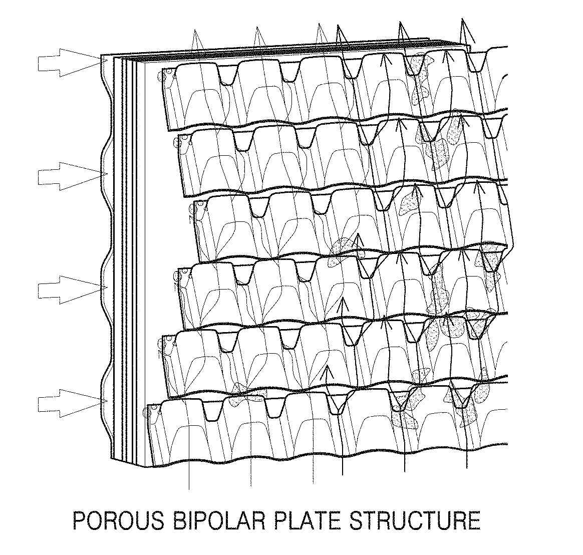
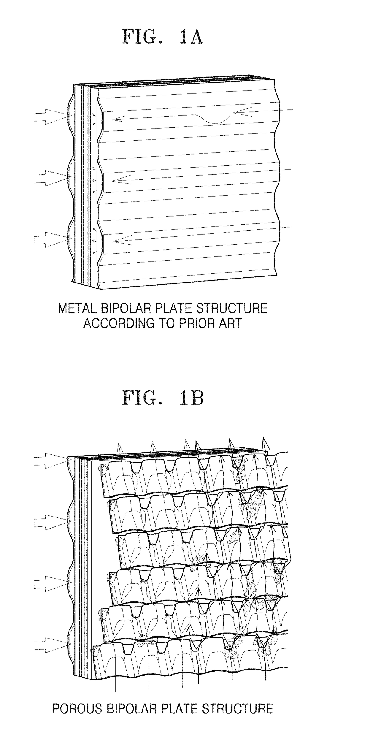
Such an intrusion causes a pressure drop in the flow fields in the bipolar plate and also increase in the power consumption of a pump.
Also, the collapse of the GDL structure due to the carbon fibers broken at the interface between the GDL and the flow fields causes degradation of the durability of the GDL and also reducing a reactive gas or the generated water transfer.

Method used


Image

  • Multi-layered carbon substrate for gas diffusion layer
  • Multi-layered carbon substrate for gas diffusion layer
  • Multi-layered carbon substrate for gas diffusion layer

Examples


preparation example 1

[0072]As raw materials, carbon staple fibers of 90 wt % with respect to a weight of entire fibers were prepared and PVA staple fibers of 10 wt % were prepared, wherein the carbon staple fibers contained carbon by 95%, had a diameter of about 7 μm, a density of about 1.81 g / cc, average lengths of about 6 mm and 12 mm, and a precursor of PAN (here, content amount ratio between the carbon staple fibers of 6 mm length and 12 mm length was 50 / 50). Then, a carbon fiber preweb was manufactured through the carbon preweb manufacturing processes, that is, fiber mixture, dispersion of fibers in water, and deposition on the wire. The carbon fibers dispersed in water were supplied to a paper-making machine via a pump. A supply unit connected to a head box of the paper-making machine had a structure that narrowed toward the head box, and the carbon fibers were arranged in parallel with a direction in which the dispersion liquid flowed. Slits between the wire and the supply unit were adjustable in...

preparation example 2

[0079]A carbon fiber preweb having a MD / TD ratio of 2.0 on the first surface and the second surface was manufactured in the same manner as in preparation example 1, except that there was no section for generating a swirl before the dispersion liquid contacted the wire and a gap between slits on a portion where the dispersion liquid initially contacted the wire was equal to the length of the carbon fiber. After that, the carbon substrate having the characteristics illustrated in Table 1 was obtained through the same processes as in preparation example 1.

example 1

[0080]Two unit carbon substrates manufactured according to preparation example 1 were stacked on each other, compressed, and dried to obtain a stacked unit carbon substrate. The stacking was performed so that a second surface of a first unit carbon substrate at an upper level and a first surface of a second unit carbon substrate at a lower level were in contact with each other.

[0081]The stacking was performed by using a paper-making machine including two head boxes. In a head box of a first zone, a first carbon fiber preweb (unit carbon substrate) was formed and placed on a pickup belt, and then, a second carbon fiber preweb (unit carbon substrate) formed in a head box of a second zone was placed on the pickup belt so that two carbon fiber prewebs can be stacked.

[0082]The dried preweb underwent a heating and pressurizing process at a temperature of about 80° C. to about 150° C. and a pressure of about 1 to about 10 kgf / cm2 and a winding process to obtain the carbon fiber preweb.

[008...


PUM


Abstract

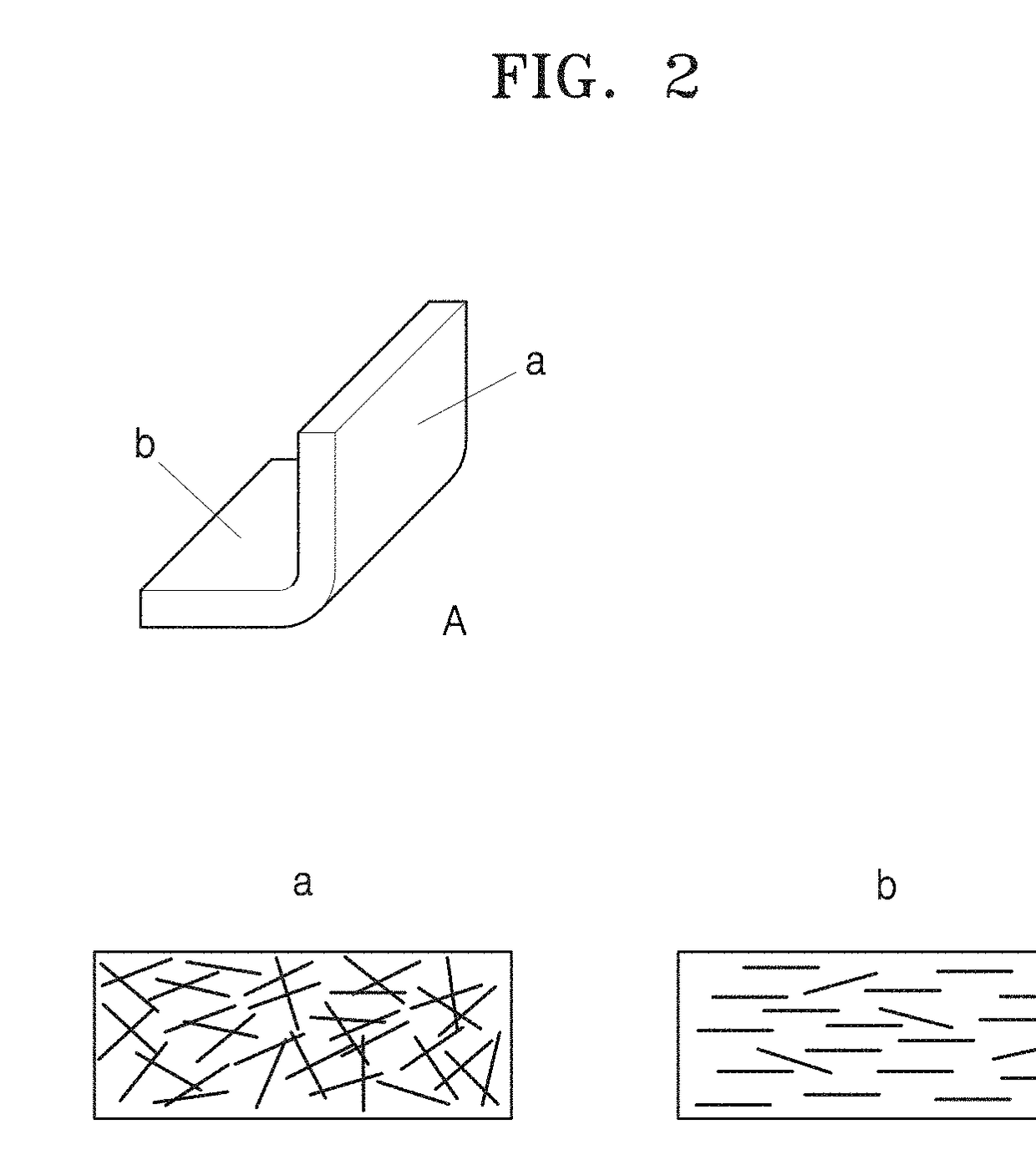
Provided is a carbon substrate for a gas diffusion layer of a fuel cell. The carbon substrate has a structure, in which a plurality of unit carbon substrates are stacked. Each of the unit carbon substrates is a plate type substrate having a first surface and a second surface opposite to the first surface. Carbon fibers are randomly arranged on the first surface of the each unit carbon substrate. The number of the carbon fibers arranged in a machine direction of the unit carbon substrate is greater than the number of carbon fibers arranged in a transverse direction of the unit carbon substrate from the first surface to the second surface along a thickness direction of the unit carbon substrate; and, accordingly, an orientation gradient, in which the orientation in the machine direction increases from the first surface to the second surface, is shown.

Description

FIELD OF THE INVENTION[0001]One or more embodiments relate to a carbon substrate for a gas diffusion layer in a fuel cell, and more particularly, to a multi-layered carbon substrate including a plurality of unit carbon substrates orientated in a machine direction (MD) and stacked on one another so that a gas diffusion layer including the multi-layered carbon substrate has increased mechanical strength and high gas diffusion performance.BACKGROUND OF THE INVENTION[0002]The inventive concept is a result of research projects supported by Korea Institute of Energy Technology Evaluation and Planning (Project ID. 2014010031880) of the Ministry of Trade, Industry and Energy.[0003]Compared to other fuel cells, a polymer electrolyte membrane fuel cell (PEMFC) has low operating temperature, high efficiency, high current density, high power density, short starting time, and a rapid response speed in response to a load change. In the PEMFC, a catalyst is respectively applied to an anode and a c...

Claims


Application Information

Patent Timeline
IPC IPC(8): H01M4/88
CPCH01M2250/20H01M4/8807H01M8/0234H01M4/861H01M4/8636H01M4/8657H01M8/10H01M2008/1095H01M2220/20Y02E60/10Y02E60/50H01M8/0245Y02T90/40
Inventor LEE, EUN SOOKKIM, EUN CHONGKIM, TAE HYUNGYANG, MIN JEEJYOUNG, JY YOUNGKIM, TAE NYUNJANG, SANG WOOK
Owner JINWOO ENG
Learn More