Zirconium-based metal-organic frameworks as catalyst for transfer hydrogenation

a metal-organic framework and catalyst technology, applied in the direction of organic compounds/hydrides/coordination complex catalysts, physical/chemical process catalysts, organic reduction, etc., can solve the problems of limiting the practical application of catalysts, affecting the application of catalytic processes for producing various platforms and value-added chemical materials directly from carbohydrates or directly from lignocellulosic biomass, and requiring enormous effort. , to achieve the effect of excellent transfer hydrogenation

Active Publication Date: 2017-11-09
KOREA RES INST OF CHEM TECH
View PDF0 Cites 30 Cited by
  • Summary
  • Abstract
  • Description
  • Claims
  • Application Information

AI Technical Summary

Benefits of technology

[0040]The metal-organic framework having a highly crystalline, porous, MOF-808 based X-ray diffraction pattern, which exhibits

Problems solved by technology

The development of a catalytic process for producing various platforms and value-added chemical materials directly from carbohydrates or directly from lignocellulosic biomass requires enormous effort.
However, the two hydrogenation strategies described above have some limitations (e.g., harsh

Method used


Image

  • Zirconium-based metal-organic frameworks as catalyst for transfer hydrogenation
  • Zirconium-based metal-organic frameworks as catalyst for transfer hydrogenation
  • Zirconium-based metal-organic frameworks as catalyst for transfer hydrogenation

Examples


preparation example 1

r)

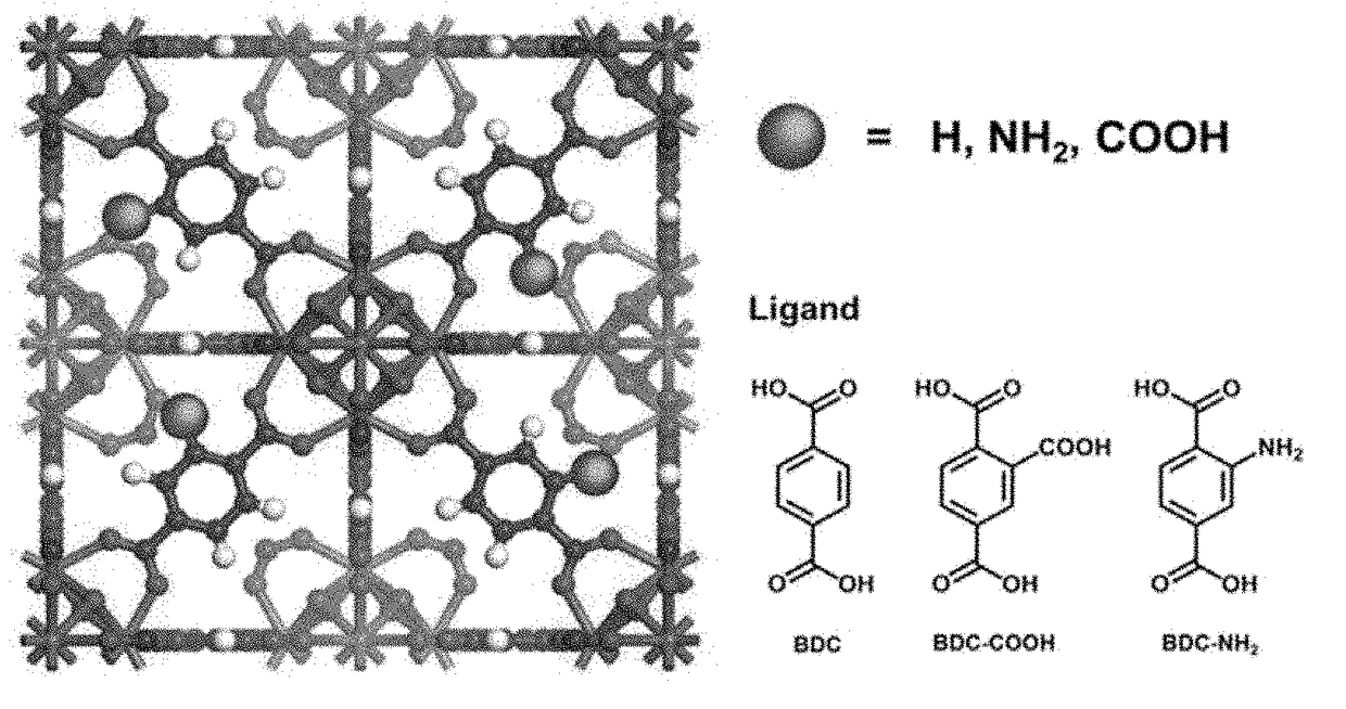
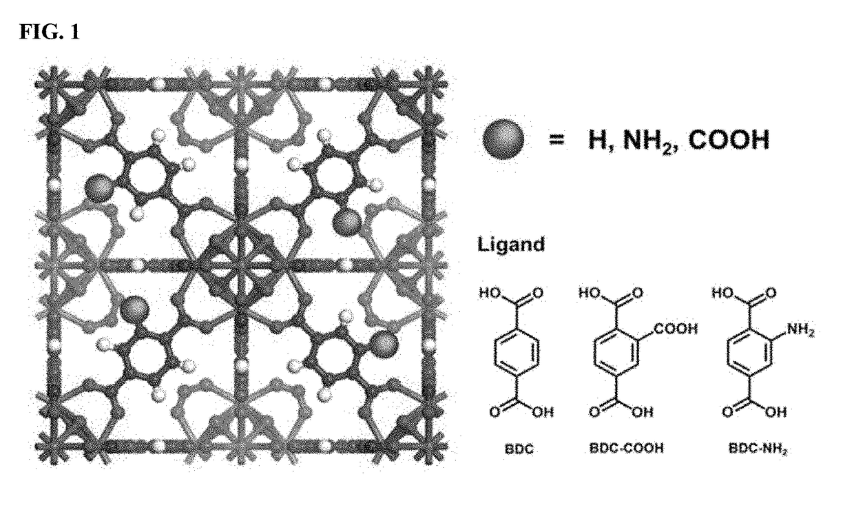
[0058]UiO-66(Zr) was synthesized by the reflux method. Specifically, H2BDC (4.62 g, 27.8 mmol) was dissolved in DMF (23.6 g, 322 mmol) in a 100 mL round flask at room temperature. Then, ZrOCl2.8H2O (8.96 g, 27.8 mmol) and 37% HCl (4.63 mL, 5.47 g, 150 mmol) were added to the mixture. The molar ratio of the final ZrOCl2.8H2O / H2BDC / DMF / HCl mixture was 1:1:11.6:5.4. The reaction mixture was vigorously stirred to obtain a homogeneous gel. The mixture was heated to 150° C. and maintained thereat for 6 hours to obtain crystalline UiO-66(Zr) solid. The thus-obtained product was recovered from the slurry, re-dispersed in DMF at 60° C. for 6 hours while stirring, and recovered by filtration. The same procedure was repeated twice using methanol instead of DMF. Finally, the solid product was dried at 100° C. overnight.

Preparation Example 2: Synthesis of UiO-66(Zr)—NH2

[0059]UiO-66(Zr)—NH2 was synthesized by the reflux method. First, 2-aminoterphthalic acid 1.94 g (10.7 mmol) was dissolved in...

preparation example 3

r)—COOH

[0060]UiO-66(Zr)—COOH was also synthesized by the reflux method. Briefly, 1,2,4-benzenetricarboxylic acid (14 g, 66.7 mmol) and ZrOCl2.8H2O (10.74 g, 33.3 mmol) were dissolved in water (30 mL) and benzoic acid (20.4 g, 166.6 mmol) in a 100 mL round flask. The molar ratio of the final ZrOCl2.8H2O / H3BTC / H2O / C6H5COOH mixture was 1:2:50:5. Then, the reaction solution was ramped to 100° C. and kept thereat for 24 hours. Post-treatment was also performed in exactly the same manner as in the procedure mentioned for UiO-66(Zr)—NH2.

preparation example 4

[0061]H3BTC (4.8 g, 0.5 mmol) and ZrOCl2.8H2O (3.3 g, 0.5 mmol) were added to a solvent mixture of DMF / formic acid (270 mL / 360 mL). The reaction mixture was transferred to a 1 L Teflon-lined pressure autoclave and heated at 135° C. for 2 days. The white precipitate was collected by centrifugation, washed in DMF for 24 hours, and washed in ethanol for 24 hours. Each solvent was replaced twice during the above period, and finally, the product was dried at 100° C. for 12 hours.


PUM

PropertyMeasurementUnit
Temperatureaaaaaaaaaa
Currentaaaaaaaaaa
Digital informationaaaaaaaaaa

Abstract

The present invention relates to a catalyst for transfer hydrogenation, which is formed of a metal-organic framework having an MOF-808 based X-ray diffraction pattern.
A high crystalline porous MOF-808 based metal-organic framework exhibits excellent performance in the transfer hydrogenation of ethyl levulinate (EL) at high and low temperature.

Description

TECHNICAL FIELD[0001]The present invention relates to a catalyst for transfer hydrogenation formed of metal-organic frameworks having an Zr-based MOF based X-ray diffraction pattern.BACKGROUND ART[0002]To solve the problems of gradual depletion of fossil fuels and worsening environmental conditions, and to meet the energy demand for improving the quality of life, studies on alternative renewable resources are under way. Among several renewable resources, only some biomass species which are inexpensive and abundant in nature are sustainable sources of supply; otherwise, most resources are conventionally derived from liquid fuels and fossil resources. The development of a catalytic process for producing various platforms and value-added chemical materials directly from carbohydrates or directly from lignocellulosic biomass requires enormous effort. Among these chemicals, γ-valerolactone (GVL) is recognized as a versatile building block that can be used as an additive in liquid fuels f...

Claims


Application Information

Patent Timeline
IPC IPC(8): C07B35/02B01J27/20C01F17/00C08F4/64
CPCC07B35/02B01J27/20C08F4/64C01F17/00B01J37/036B01J37/06B01J35/002B01J35/1023B01J35/1028B01J35/1047B01J31/1691B01J31/2239B01J2231/643B01J2531/0216B01J2531/48C07D307/32C07D307/44B01J31/26
Inventor HWANG, YOUNG KYUCHANG, JONG SANHONG, DO YOUNGHWANG, DONG WONLEE, U HWANGCHO, KYUNG HOVALEKAR, ANIL HARIBHAULEE, SU KYUNG
Owner KOREA RES INST OF CHEM TECH
Why Eureka
Try Eureka