Method for controlled growth of carbon nanotubes in a vertically aligned array

a carbon nanotube and vertical alignment technology, applied in the manufacture of electric discharge tubes/lamps, electrode systems, semiconductor/solid-state device details, etc., can solve the problems of increasing temperature rise and device failure rate, limiting device performance, and reducing the nucleation site so as to prevent the al surface from premature oxidation, reduce the density of carbon nanotubes, and control the effect of carbon nanotube nucleation sites

Inactive Publication Date: 2017-11-30
NAT TECH & ENG SOLUTIONS OF SANDIA LLC
View PDF0 Cites 12 Cited by
  • Summary
  • Abstract
  • Description
  • Claims
  • Application Information

AI Technical Summary

Benefits of technology

[0009]The present invention is directed to the template-guided chemical vapor deposition (CVD) growth of carbon nanotubes using anodized aluminum oxide (AAO) nanopore templates. According to the present invention, vertically aligned, untangled planarized arrays of multiwall carbon nanotubes (MWNTs) with Ohmic back contacts can be grown in nanopore templates on arbitrary substrates. The templates can be prepared by sputter depositing Al films onto W-coated substrates, followed by anodization to form an aluminum oxide nanopore array. Small amounts of rare-earth metal doping in the Al, such as 2 wt. % Nd, can prevent the Al surface from prematurely oxidizing upon exposure to air prior to anodization. The substrate may be selected based on the desired properties for a given application since the tungsten underlayer provides the electrical access to the nanotubes. The tungsten underlayer helps eliminate the aluminum oxide barrier that typically occurs at the nanopore bottoms by instead forming a thin WO3 layer. The WO3 can be selectively etched to enable electrodeposition of metal catalysts in the nanopores, necessary to grow MWNTs, with control over the catalyst site density. Many materials have been reported as catalysts for the growth of MWNTs; the mo...

Problems solved by technology

Removing heat generated by high-power electronics is often a limiting factor in device performance.
Heat removal with existing TIMs is not good enough in many power electronics applications.
Both temperature rise and device failure rate increase when low thermal conductivity TIM materials are used.
Therefore, as shown in FIG. 3, device failure rates are a problem when the TIM ...

Method used


Image

  • Method for controlled growth of carbon nanotubes in a vertically aligned array
  • Method for controlled growth of carbon nanotubes in a vertically aligned array
  • Method for controlled growth of carbon nanotubes in a vertically aligned array

Examples


Embodiment Construction

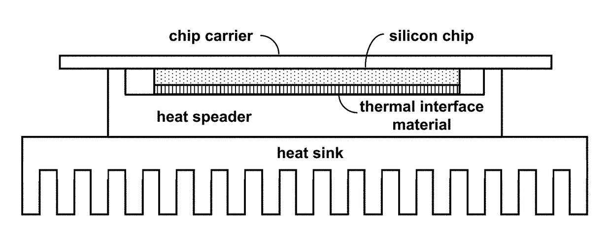
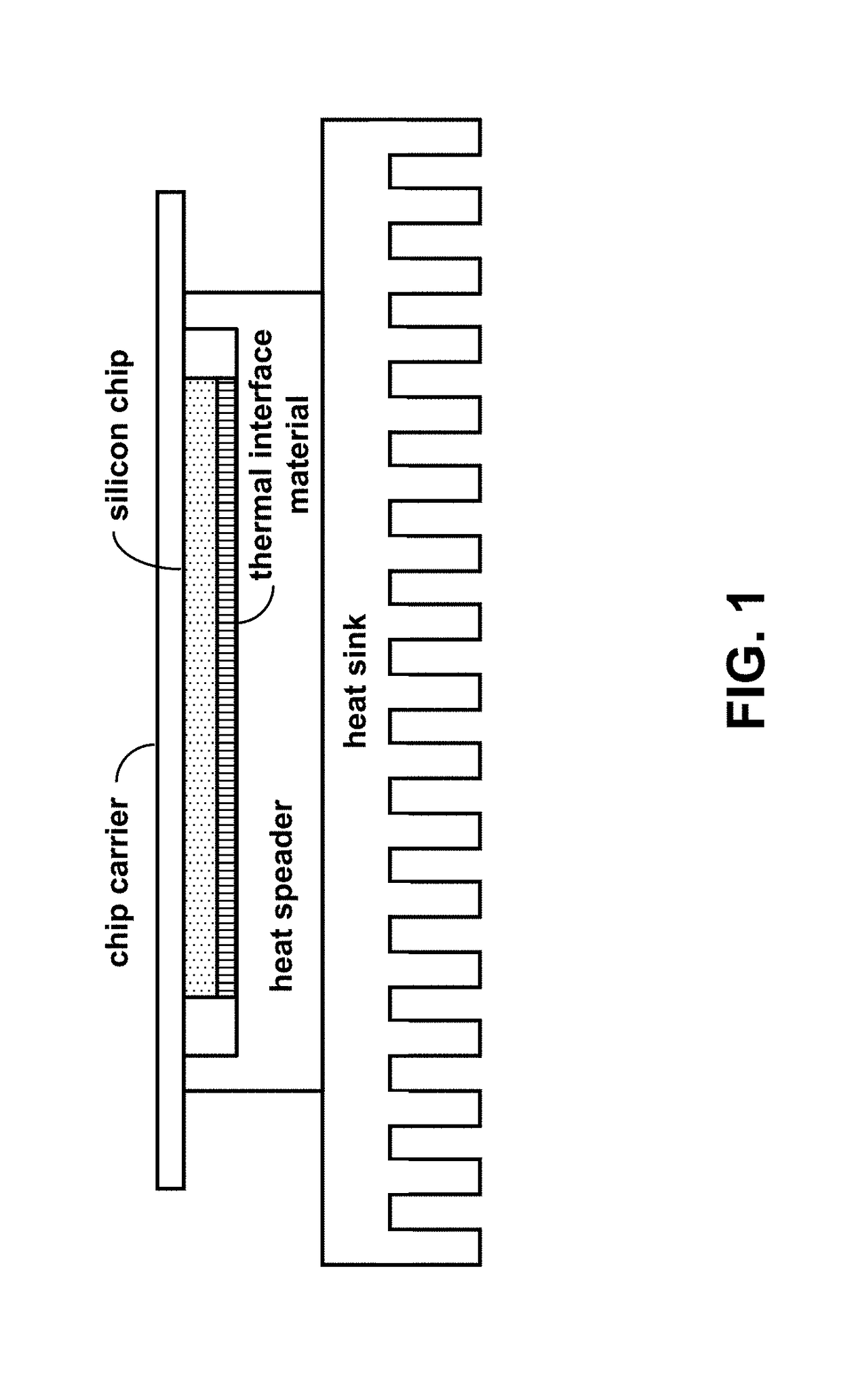
[0027]FIG. 4 shows an example of a carbon-nanotube-based TIM. The carbon-nanotube-based TIM has no epoxy in the thermal pathway, thereby enabling a high thermal conductivity and, therefore, high heat flux from a heat-generating device to a thermal spreader heat sink. FIG. 5 is a graph of the TIM thermal conductivity as a function of carbon nanotube (CNT) thermal conductivity for various contact areas. As can be seen, high quality CNTs can provide adequate TIM thermal conductivity, even with a low contact area. An optimal CNT-TIM preferably has no adhesives in the thermal pathway, a high CNT site density to increase the number of thermal pathways (i.e., no entanglement), planarized array tips to maximize thermal contacts to the hot device surface, and high-crystalline quality CNTs to provide a high thermal conductivity. As shown in FIG. 6, high density aligned arrays of CNTs can be grown using anodized aluminum oxide (AAO) nanopore templates on heat sink substrates (alternatively, ar...


PUM

PropertyMeasurementUnit
Diameteraaaaaaaaaa
Lengthaaaaaaaaaa
Electrical conductivityaaaaaaaaaa

Abstract

Template-guided growth of carbon nanotubes using anodized aluminum oxide nanopore templates provides vertically aligned, untangled planarized arrays of multiwall carbon nanotubes with Ohmic back contacts. Growth by catalytic chemical vapor deposition results in multiwall carbon nanotubes with uniform diameters and crystalline quality, but varying lengths. The nanotube lengths can be trimmed to uniform heights above the template surface using ultrasonic cutting, for example. The carbon nanotube site density can be controlled by controlling the catalyst site density. Control of the carbon nanotube site density enables various applications. For example, the highest possible site density is preferred for thermal interface materials, whereas, for field emission, significantly lower site densities are preferable.

Description

CROSS-REFERENCE TO RELATED APPLICATION[0001]This application claims the benefit of U.S. Provisional Application No. 62 / 342,083, filed May 26, 2016, which is incorporated herein by reference.STATEMENT OF GOVERNMENT INTEREST[0002]This invention was made with Government support under Contract No. DE-NA0003525 awarded by the United States Department of Energy / National Nuclear Security Administration. The Government has certain rights in the invention.FIELD OF THE INVENTION[0003]The present invention relates to methods to grow carbon nanotube arrays and, in particular to methods that provide independent control of the crystalline quality of individual carbon nanotubes in a vertically-aligned array as well as control of the average spacing between such nanotubes in the array.BACKGROUND OF THE INVENTION[0004]There are many potential applications for the use of vertically-aligned arrays of carbon nanotubes. A partial list includes thermal interface materials (TIMs), cold-cathode electron fi...

Claims


Application Information

Patent Timeline
IPC IPC(8): C23C16/26C23C16/44C25D3/12C25D5/48H01L23/373C25D11/04C25D5/02B82Y30/00B82Y40/00H01J1/304
CPCC23C16/26H01L23/3738C23C16/44C25D3/12C25D5/022C25D11/045H01J1/304Y10S977/742Y10S977/833Y10S977/843B82Y30/00B82Y40/00C25D5/48C25D11/04C25D11/20C25D11/24C23C16/0281C23C16/56H01J9/025C01B32/162C01B32/176H01L2224/29193H01L2924/10253H01L23/373H01L23/3736H01L23/42H01J2201/30469
Inventor SIEGAL, MICHAEL P.FRIEDMAN, CAITLIN ROCHFORDYELTON, WILLIAM G.
Owner NAT TECH & ENG SOLUTIONS OF SANDIA LLC
Why Eureka
Try Eureka