
Process for Forming Reinforced Rocker Panel Assembly

Active Publication Date: 2017-12-14
VAN ROB
View PDF3 Cites 0 Cited by
  • Summary
  • Abstract
  • Description
  • Claims
  • Application Information

AI Technical Summary

Benefits of technology

This patent is about a process for making reinforced metal devices, like rocker panels, that overcome the shortcomings of existing methods. The process reduces internal stresses, deformations, and loss of strength and shape. It also improves the workability, formability, and bendability of the reinforcement patch when combined with a blank metal sheet. The process includes a two-step welding approach that securely attaches the reinforcement patch to the rocker panel. The process also allows for the use of metal blanks of reduced gage thicknesses and improved physical contact between the reinforcement patch and the rocker panel after bending.

Problems solved by technology

With increased tensile strength, however, the steel materials may suffer disadvantages in that material flatness, formability and joint strength may be reduced.
Even with patch type reinforcement, however, increasing metal strength grades remains to provide challenges with respect to formability and bendability, especially in forming structural components requiring heavily formed profiles or bend angles.
It has been appreciated that such joining solutions of Cape may not be practical, and become increasingly unworkable for higher bend angles and material strength for configurations, bending processes and applications such as a vehicle rocker panel.
Severe residual stresses can remain after bending, compromising the structural and dimensional integrity of the structure.
However, significant material thinning can be anticipated, predominantly in the in outer sheet relative to the bend line and good potential for damage within surrounding sheet securement welds / integration.
It has been appreciated to be also difficult and expensive to achieve material properties at full potential and distortion control due to non-uniform heating and quenching in the post form heat treating process.
The process is relatively complex and high cost.

Method used


Image

  • Process for Forming Reinforced Rocker Panel Assembly
  • Process for Forming Reinforced Rocker Panel Assembly
  • Process for Forming Reinforced Rocker Panel Assembly

Examples


Embodiment Construction

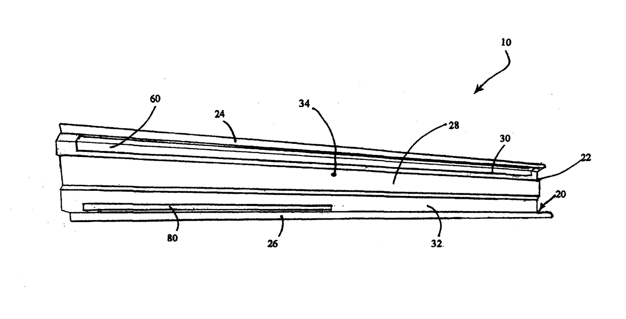
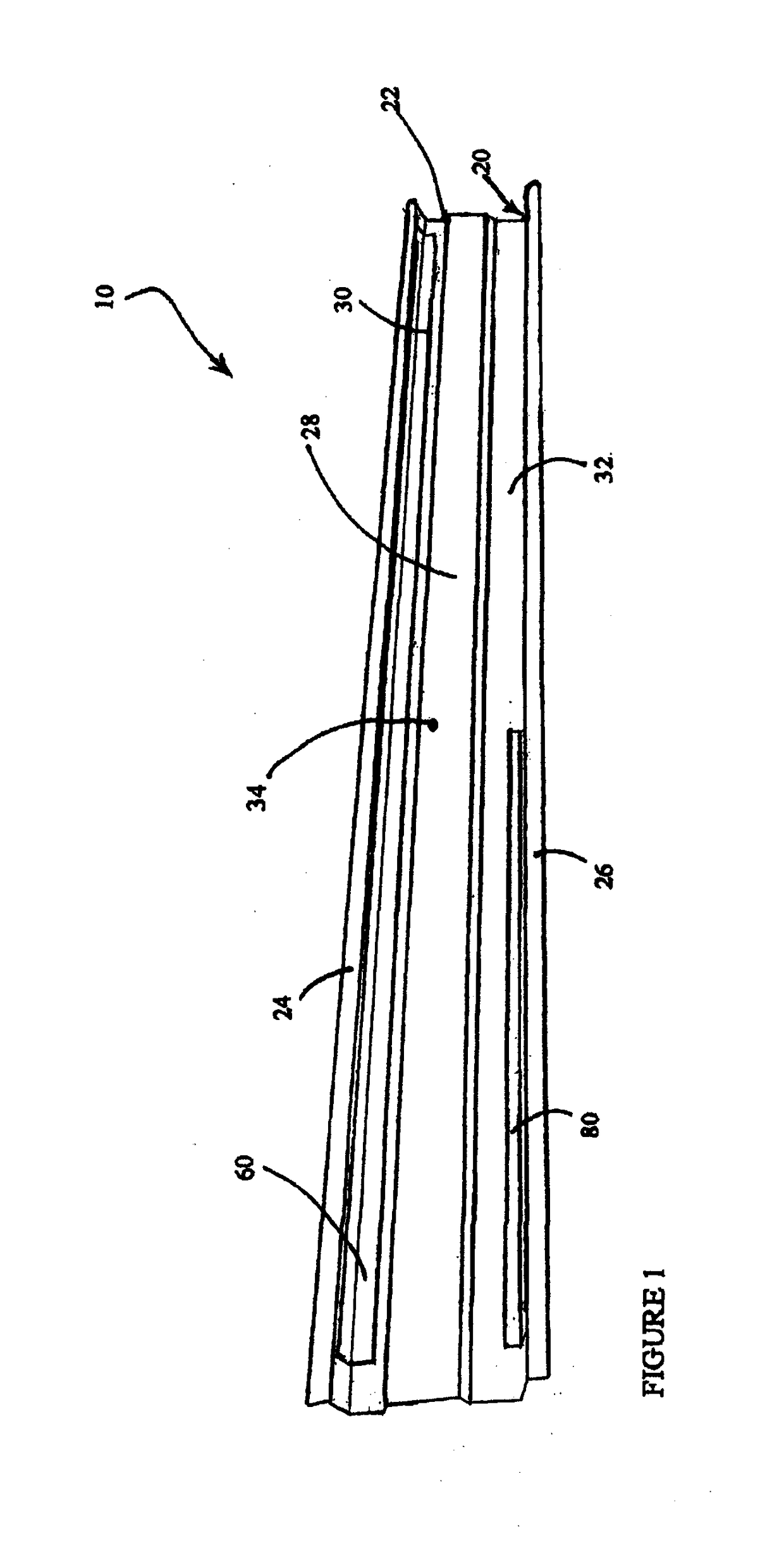
[0039]Reference is made to FIG. 1 which shows a perspective view of a reinforced inner rocker panel 10 as prepared by a process in accordance with a preferred embodiment of the present invention. As will be further described below, the inner rocker panel 10 includes an elongated rocker panel beam 20, and first and second corner reinforcement patches 60, 80 shown in FIG. 1 as being welded to the rocker panel beam 20.

[0040]The rocker panel beam 20 has a generally “U”-shaped cross sectional profile, so as to include a generally rectangular base beam portion 22, and a pair of opposed lateral flanges 24, 26 integrally coupled to associated longitudinal edges of the base beam portion 22 to cooperatively define an inward channel therebetween. For additional rigidity and strength, a strengthening rib 28 is integrally formed along a length of the base beam portion 22 to extend towards the inward channel, thereby forming a pair of laterally extending webs 30, 32 interposed between the strengt...


PUM

PropertyMeasurementUnit
Thicknessaaaaaaaaaa
Thicknessaaaaaaaaaa
Angleaaaaaaaaaa

Abstract

In a preferred embodiment, there is provided a process for forming a reinforced rocker panel assembly, and which includes positioning a reinforcement patch having first and second patch sections in surface-to-surface contact with a blank panel sheet, and welding the first patch section to the blank panel sheet. The process further includes bending both the blank panel sheet and the reinforcement patch along a bend line interposed between the first and second patch sections to form the blank panel sheet into a rocker panel portion having an elongated base section and a longitudinal flange, where the first and second patch sections are in at least partial abutting contact with the base section and the flange. The process also includes welding the second patch section to the flange.

Description

SCOPE OF THE INVENTION[0001]The present invention relates to a process for forming a reinforced rocker panel assembly, preferably a reinforced inner rocker panel assembly, comprising a rocker panel portion and at least one reinforcement patch welded to the rocker panel portion, and which preferably includes two separate welding steps for welding two different sections of the reinforcement patch to the rocker panel portion before and after cold forming.BACKGROUND OF THE INVENTION[0002]Passenger vehicles typically include a number of structural components, such as a rocker or rocker panel (hereinafter referred to as “rocker panel”). A rocker panel is a longitudinally extending side structural component normally designed to integrally join to a lower body structure of a vehicle, and to fit below the base of a door opening and between wheel wells. A rocker panel is intended to provide strength and stiffness to a vehicle body, and forms part of integral Body in White (“BIW”) structural c...

Claims


Application Information

Patent Timeline
IPC IPC(8): B62D65/02B23K33/00B23K101/00
CPCB62D65/024B23K2201/006B23K33/002B62D25/025B23K2101/006
Inventor LINDGREN, BO AXELZENG, CHENGMCCABE, DAVID JOHNKAVANAUGH, BARRY THOMAS
Owner VAN ROB
Learn More