Real-time imaging system for monitoring and control of thermal therapy treatments

a real-time imaging and treatment technology, applied in the field of real-time imaging system for monitoring and controlling of thermal therapy treatments, can solve the problems of cumbersome and expensive current standard of mri-based thermal monitoring, and achieve the effects of improving outcomes, safe, rapid and precise adjuvant hyperthermia, and increasing the effectiveness of other treatment methods

Active Publication Date: 2018-01-25
UNIV OF SOUTHERN CALIFORNIA
View PDF0 Cites 7 Cited by
  • Summary
  • Abstract
  • Description
  • Claims
  • Application Information

AI Technical Summary

Benefits of technology

[0011]A closed-loop, noninvasive focused microwave thermal therapy system has been developed. The system is capable of safe, rapid, and precise adjuvant hyperthermia, neoadjuvant hyperthermia, and thermal ablation. Innovations in thermal monitoring and focusing enable improved outcomes in the fastest growing segment of the nonvascular interventional radiology device market.
[0012]Thermal therapy has primarily been used to increase the effectiveness of other treatment methods (for example, hyperthermia to enhance chemotherapy). However, recently thermal therapy has also been used to deliver localized therapeutic agents to a target region as well as for thermal ablation. Hyperthermia employs a thermal dose that is generally safe for normal cells (for example, ˜43° C.). However, hyperthermia has the potential for the following therapeutic effects: (1) thermal damage or weakening of cancer cells; (2) increased blood flow through weakened tumor (enhanced delivery of therapeutic agents); (3) increased oxygen levels in tumors; (4) stimulated immune response; and (5) thermal release of therapeutic agents encapsulated in temperature sensitive liposomes. Thermal ablation employs more extreme temperature levels (for example, >60° C. for RF, microwave and <0° C. for cryoablation) to destroy tissue. Localization of the damage is achieved using an invasive probe (radiofrequency ablation) or catheter (cryoablation), or through focusing (HIFU, microwave).
[0014]At this time, the main application for thermal therapy systems is to improve local control while limiting radiation doses using concurrent hyperthermia with re-irradiation therapy. Hyperthermia has been demonstrated to enhance radiation-induced cell killing. Additionally, several randomized trials have shown an improvement in local control when combined with re-irradiation therapy. By potentiating the effect of radiation, hyperthermia may potentially result in similar tumor control rates with lower overall doses, thereby decreasing the risks associated with re-irradiation therapy. There has also been interest in using neoadjuvant hyperthermia to reduce tumor size prior to surgery. Beyond hyperthermia applications, ablative treatments have been gaining increasing attention as an alternative to standard surgical therapies, as thermal ablation has the potential to reduce morbidity and mortality in comparison with standard surgical resection and has the ability to treat patients with contraindication or those who refuse open surgery. Lastly, thermal therapy has the potential for use in locally targeted drug delivery, in the cosmetic market, and there is emerging interest in the role of thermal devices in triggering an immune-response to cancer.
[0018]Accordingly, embodiments described herein provide methods and systems that integrate electromagnetic modeling with hardware design to achieve both focused microwave thermal therapy with real-time monitoring in the same system. Focusing is achieved with numerous independently sourced antennas (for example, 36 or 48 antennas) that surround the treatment area and radiate into an enclosure of known construction. The enclosure allows precise electric field modeling of each antenna. The models are used to determine the exact antenna sourcing in order to position, shape, and steer the focal spot as desired. By this method, 3 cm focal spot sizes with better than 1 cm position accuracy may be guaranteed while eliminating unwanted hot spots. The system may focus microwave radiation at one point or many points in a single session. The fine control of the spot location also makes faster scanning possible in order to achieve uniform hyperthermia over large tissue regions, which is not achievable by current systems. The use of many antennas increases the power output, reducing treatment time.
[0020]Embodiments described herein relate to a focused microwave thermal therapy system that utilizes a novel method of integrated real-time microwave thermal monitoring to precisely adjust the amplitude and phase output of custom high power microwave modules. This integrated solution enables on-the-fly optimization of focal spot localization, uniformity of heating, and hotspot minimization based on continuous feedback from (1) microwave thermal mapping and (2) output power monitoring.
[0027]Features of the embodiments described herein include: (1) integrated thermal monitoring, which eliminates the need for additional hardware to monitor thermal therapy delivered by focused microwave heating; (2) custom microwave hardware with full per channel control of magnitude and phase, which allows for real-time monitoring and control of focused microwave therapy array; and (3) the coupling of (i) integrated real-time thermal monitoring with (ii) real-time monitoring and control of the microwave therapy array, which enables real-time, automated enhancement of focused microwave therapy for optimum delivery of thermal dose with minimal operator intervention, all in a noninvasive manner.

Problems solved by technology

The current standard of MRI-based thermal monitoring is cumbersome, expensive, and requires the therapy system design to be MR-compatible.

Method used


Image

  • Real-time imaging system for monitoring and control of thermal therapy treatments
  • Real-time imaging system for monitoring and control of thermal therapy treatments
  • Real-time imaging system for monitoring and control of thermal therapy treatments

Examples


example 1

A. Example 1

[0283]First, the numerical vector Green's function is validated in simulation by comparing the simulated S-parameter and the predicted S-parameter from two dielectric objects under waveport source excitation. The simulation domain is shown in FIG. 41. In the simulation region, there are two PEC walls of size 130×70×20 mm3 facing each other 160 mm apart. Within the PEC walls, there are two rectangular apertures. One aperture on the left of FIG. 41 is waveport 1, which has the size of WR-340 waveguide and serves as the transmitter. Another aperture on the right of FIG. 41 is waveport 2, which has the size of WR-430 waveguide and serves as the receiver. Two dielectric objects, which are used to generate the scattered S-parameter, are placed in the middle of the two waveports. One is a rectangular box with dimension 40×40 mm2 and a dielectric constant of 2. On top of the rectangular box, there is a dielectric ball with radius of 20 mm and dielectric constant of 4. The remain...

example 2

B. Example 2

[0286]In this example, the numerical vector Green's function in measurement with a dielectrically loaded two-probe fed rectangular waveguide is validated. The waveguide is hollow brass with WR-187 specifications and an outer dimension of 2.54×5.08×15.2 cm3. The two probes are coaxial SMA extended Teflon flange mount connectors. As shown in FIGS. 43A-43B, probe 1 is located 1.91 cm inward from one corner along both axes and probe 2 is located 2.54 cm and 1.27 cm from the other corner. Here the coaxial feed of probe 1 is waveport 1, and the coaxial feed of probe 2 is waveport 2. Both the excited source at waveport 1 and the received field in waveport 2 are in the TEM mode. The nylon block, which produces the scattered S-parameter has a dimension of 2.40×1.45×5.05 cm3 and a dielectric constant of 3.1.

[0287]The measurement is performed with the vector network analyzer from 3 to 6 GHz with a frequency step of 50 MHz. The whole waveguide is surrounded by microwave absorber. To...

example 3

C. Example 3

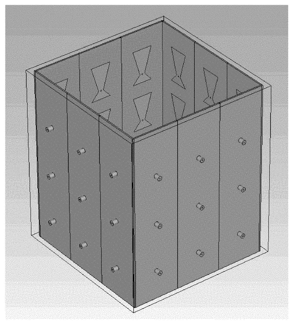
[0289]In this example, the numerical vector Green's function in measurement with a square imaging cavity is validated. The imaging cavity is built for inverse scattering experiments and has an outer dimension of 12.2×12.2×15.2 cm3. The four panels of the square cavity are made of Roger 3010 substrate with a thickness of 50mil and dielectric constant of 10.2. There are 36 tapered patch antennas printed on the inside of the 4 panels, and their dimensions are shown in FIGS. 46A-46B. The antennas are designed to radiate into an emulsion fluid coupling material and their resonance frequency is 920 MHz. The measurement is performed near the resonance frequency of the antenna from 900 to 950 MHz with a 2 MHz frequency step. Within this frequency range, the emulsion fluid is measured to have a dielectric constant εr of 19.5 and a conductivity σ of 0.075 s / m. A Nylon block with a dimension of 5.1×5.1×7.9 cm3 and a dielectric constant of 3.1 is placed in the center of the imaging ...


PUM


Abstract

Methods and systems of monitoring and controlling thermal therapy treatments. One method includes determining, with an electronic processor, a propagation constant for a plurality of waveports. The method also includes modeling an object within an imaging cavity using a sparse mesh model. The method also includes determining a simulated impedance of the object based on the model of the object. The method also includes calibrating the simulated impedance with a theoretical impedance numerically calculated for the object. The method also includes determining a distribution of an electric field and a distribution of a magnetic field for a mode in a conformal modeled waveport based on the calibrated impedance and the model of the object. The method also includes exciting the plurality of waveports to generate the determined distribution of the electric field and the distribution of the magnetic field.

Description

CROSS-REFERENCE TO RELATED APPLICATION(S)[0001]This application is a non-provisional of and claims priority to U.S. Provisional Patent Application No. 62 / 365,927, filed on Jul. 22, 2016, the entire contents of which is hereby incorporated by reference.STATEMENT REGARDING FEDERALLY SPONSORED RESEARCH OR DEVELOPMENT[0002]This invention was made with government support under No. 53-4502-6382 awarded by the U.S. Department of Defense and under No. W81XWH-10-1-0514 awarded by the Army Medical Research and Materiel Command. The government has certain rights in the invention.BACKGROUND OF THE INVENTION[0003]Thermal therapy is a fast-growing and increasingly versatile category of treatments in the fight against cancer. Researchers have developed a number of methods (both invasive and noninvasive) to deliver thermal energy in a variety of forms (including ultrasound, radiofrequency, microwave, and laser). Common to all of these thermal therapies, however, is the necessity for real-time therm...

Claims


Application Information

Patent Timeline
Patent Type & Authority Applications(United States)
IPC IPC(8): A61B5/01A61B5/00A61B5/055
CPCA61B5/015A61B5/055A61B5/0033A61B8/463A61B5/4836A61B5/7275A61B2576/00G16H30/40A61B5/0036
Inventor STANG, JOHN P.HAYNES, MARK S.MOGHADDAM, MAHTA
Owner UNIV OF SOUTHERN CALIFORNIA
Why Eureka
Try Eureka