
Software-Defined Implantable Ultrasonic Device for Use in the Internet of Medical Things

a technology of implantable ultrasonic devices and medical things, which is applied in the field of software-defined implantable ultrasonic devices for use in the internet of medical things, can solve the problems of increasing the battery size reducing the battery life of the implantable device, and prohibiting continuous telemetry operation

Active Publication Date: 2018-01-25
NORTHEASTERN UNIV
View PDF14 Cites 19 Cited by
  • Summary
  • Abstract
  • Description
  • Claims
  • Application Information

AI Technical Summary

Benefits of technology

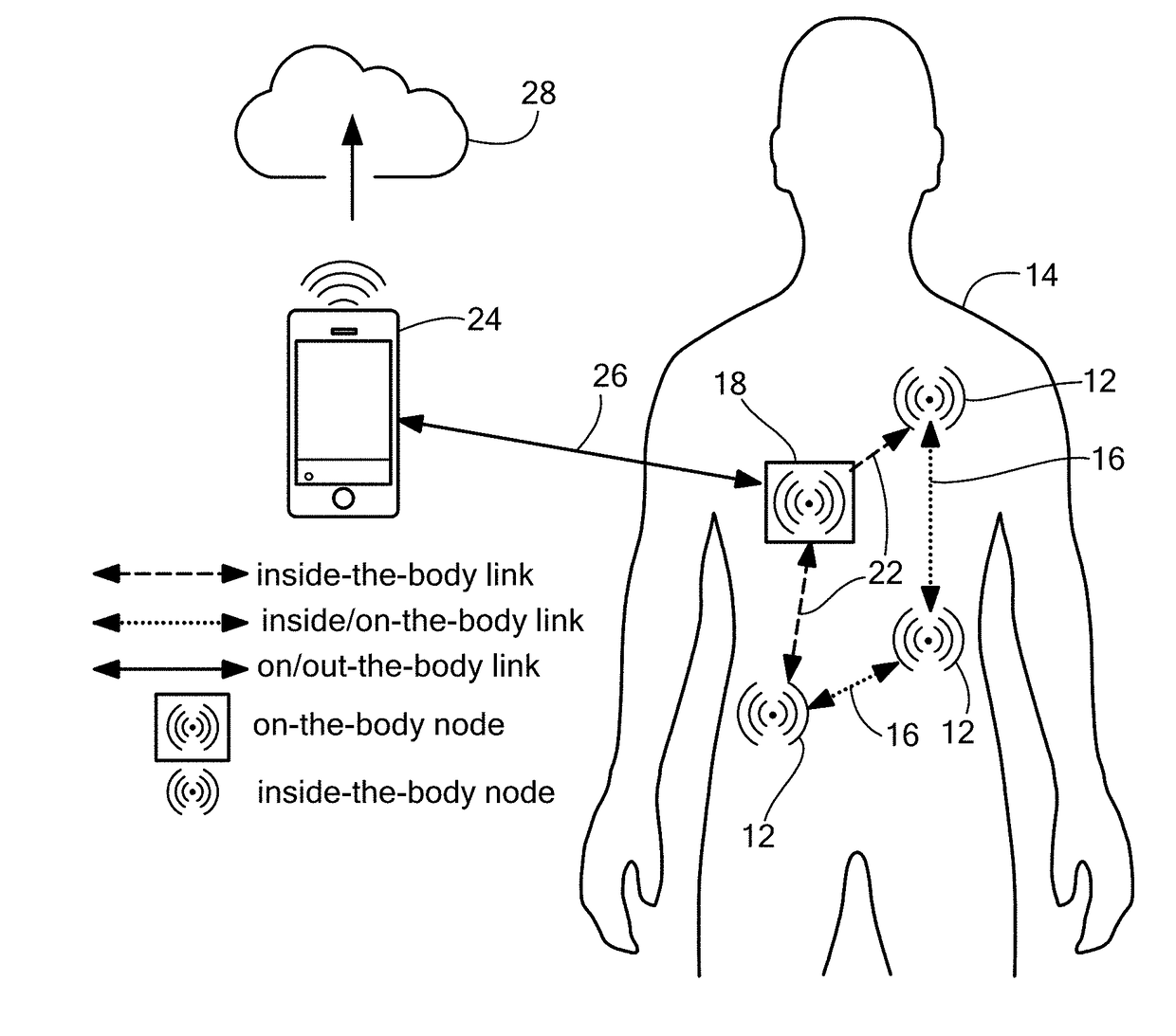
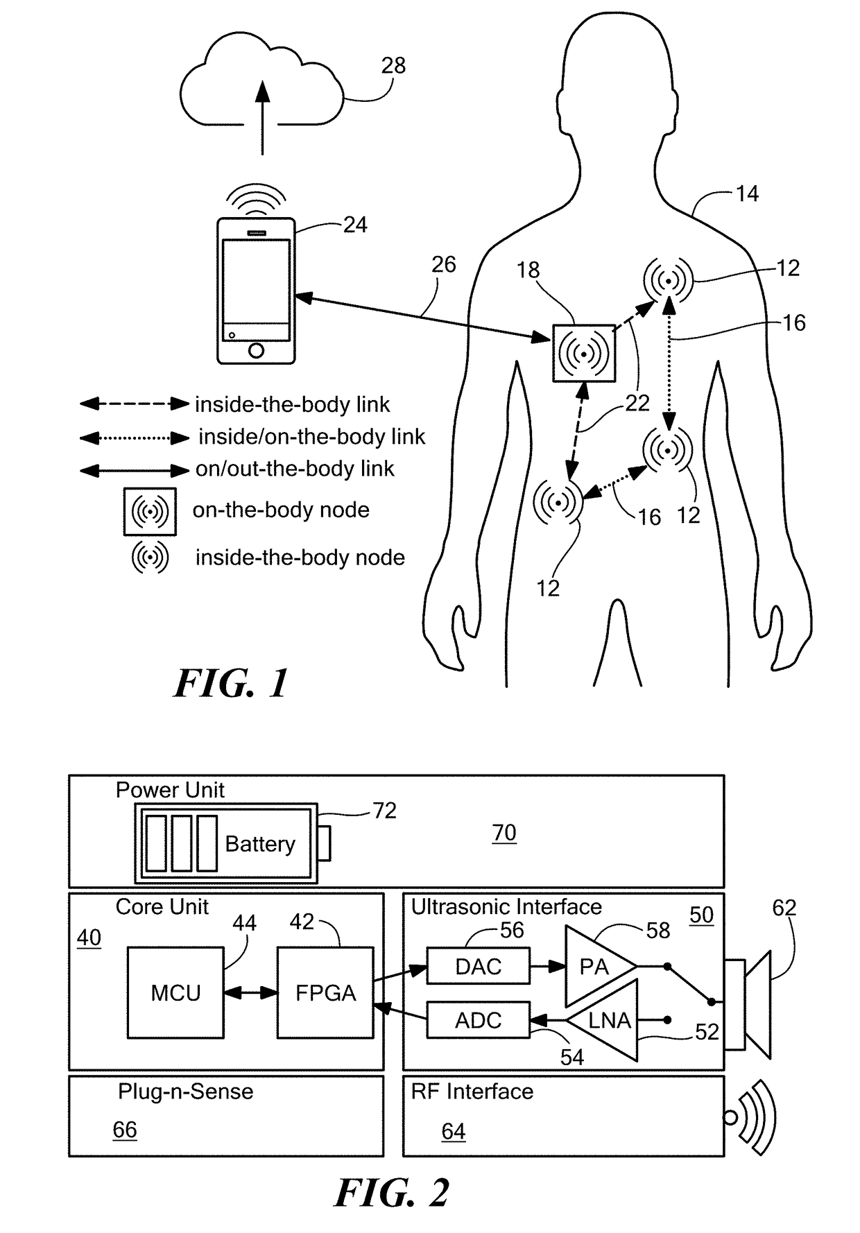
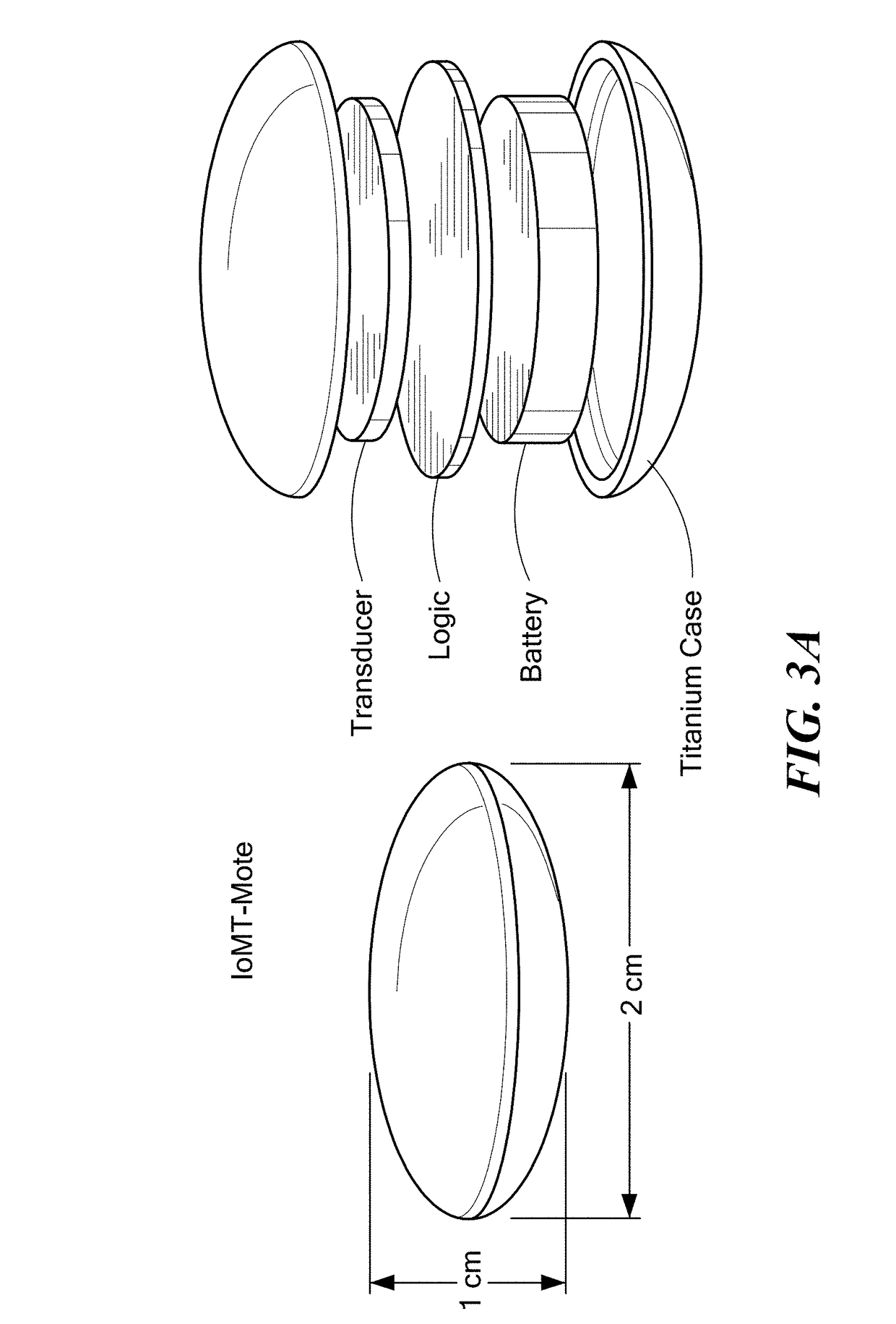
The patent describes an Internet of Medical Things (IoMT) platform that allows for ultrasonic communication between devices in the body. The platform is flexible and adaptable to different requirements, making it ideal for closed-feedback loop applications. The platform includes a modular and reconfigurable hardware and software architecture that can be adapted to different needs. The devices are small, energy-efficient, and resource-constrained, making them ideal for use in wearable and implantable medical devices. The platform also includes a communication unit and a wearable patch that can communicate with each other through ultrasounds. The devices can be used for real-time remote monitoring of biological parameters and can trigger sampling operations and process the data collected through on-board sensors. The platform has been tested in animal models and is currently being used in clinical trials. The patent also describes the reconfiguration capabilities of the platform and the various sensors and actuators that can be used with it.

Problems solved by technology

Unfortunately, the dielectric nature of the human body poses a key obstacle to enabling this vision of networked implantable devices.
This reduces the battery lifetime (or, equivalently, increases the battery size) of the implantable device, in a domain where low power, miniaturization, and battery duration are major concerns.
To put this in context, state-of-the-art pacemakers require power in the order of μW for pacing, while a commercial RF transceiver for an implant operates with power in the order of tens of mW, making continuous telemetry operation prohibitive.
As a consequence, in state-of-the-art pacemakers, the battery alone often occupies two thirds of the entire volume of the implant.

Method used


Image

  • Software-Defined Implantable Ultrasonic Device for Use in the Internet of Medical Things
  • Software-Defined Implantable Ultrasonic Device for Use in the Internet of Medical Things
  • Software-Defined Implantable Ultrasonic Device for Use in the Internet of Medical Things

Examples


example 1

Energy Consumption

[0184]In this section, the energy consumption of the hardware of the IoMT-mote prototype is presented. Measurements were performed using a custom current sensing system based on the shunt resistor method. The shunt resistor method comprised sensing a current by measuring voltage drop along a small resistor, i.e., the shunt resistor, connected in series between the power supply and the load, i.e., the device under test (DUT). By dividing the voltage drop by the value of the shunt resistor, I=V / R, the current flowing through the resistor, and thus the current drawn by the DUT, was obtained. FIG. 11 shows a diagram of the measurement setup. In this setup, the voltage drop was measured using two analog inputs of the Saleae Logic Pro 8 logic analyzer to capture voltages at the two ends of a 1Ω shunt resistor. The voltage measures, sampled at 12.5 MHz, were saved on a host computer and exported to Matlab for processing; the voltage drop was obtained as the difference bet...

example 2

on Loss

[0195]FIG. 12 shows attenuation loss in pork meat for RF waves at 2.4 GHz and for ultrasonic waves at 700 kHz. The attenuation included absorption by tissue, conversion losses and spread losses. Measurements were performed by gradually increasing the amount of pork meat between the transmitting and receiving antenna, or transducer. For the RF measurements, the received power was measured by the CC2650 MCU, while for the ultrasonic measurements prototype, the received power was measured using the Saleae Logic Pro 8 logic analyzer. To avoid RF leakages that can affect the measurement results, the two CC2650 boards were enclosed inside two Faraday shielding bags to attenuate up to 82 dB the RF leakage and therefore reduce the undesired effect of in-air RF propagation. FIG. 13 shows an example of the RF measurement setup. It was observed that for 2 to 12 cm propagation distance, RF attenuation was 55 to 80 dB higher than the ultrasonic attenuation.

example 3

-Rate Evaluation

[0196]This example describes the performance the UsWB transmission scheme implementation on the IoMT-mote in terms of bit-error-rate as a function of the transmission power in different use-case scenarios. Ultrasonic phantoms were used that matched the acoustic properties of different human tissues, e.g., soft tissues, bones, and fluids. Specifically, an upper arm phantom and a thoracic phantom were used. The upper arm phantom emulated muscle tissue containing veins with fluid simulating blood. The thoracic phantom included the mid thoracic spinal segment containing spinal fluid, muscle, skin and other soft tissues. FIG. 14 shows the channel impulse response (CIR) of the two considered scenarios. The point at time=0 ms indicates the instant of transmission; the other points represent the time of arrival of the signal paths. It was observed that in the upper arm phantom almost no multipath effect was experienced, except for a secondary path caused by the reflection of...


PUM


Abstract

Implantable and wearable devices and system for transmitting signals ultrasonically through biological tissue are implemented based on an Internet of Medical Things (IoMT) platform software and hardware architecture. The devices are size-, energy-, and resource-constrained and implement ultrasonic communication protocols and communicate with each other through ultrasound.

Description

CROSS REFERENCE TO RELATED APPLICATIONS[0001]This application claims priority under 35 U.S.C. §119(e) of U.S. Provisional Application No. 62 / 376,027, filed on Aug. 17, 2016, entitled “Software-Defined Implantable Ultrasonic Device for Use in the Internet of Medical Things,” the disclosure of which is hereby incorporated by reference.[0002]This application claims priority under 35 U.S.C. §120 of U.S. patent application Ser. No. 15 / 546,423, filed on Jul. 26, 2017, entitled “Internet-Linked Ultrasonic Network for Medical Devices,” which is a national phase entry under 35 U.S.C. §371 of International Application No. PCT / US2016 / 014860, filed on Jan. 26, 2016, which claims priority under 35 U.S.C. §119(e) of U.S. Provisional Application No. 62 / 107,737, filed on Jan. 26, 2015, the disclosures of which are hereby incorporated by reference.STATEMENT REGARDING FEDERALLY SPONSORED RESEARCH OR DEVELOPMENT[0003]N / ABACKGROUND[0004]Wirelessly networked systems of implantable medical devices endowe...

Claims


Application Information

Patent Timeline
Patent Type & Authority Applications(United States)
IPC IPC(8): H04L29/08A61B5/00H04B1/3827H04B11/00H04B13/00
CPCH04L67/12H04B11/00H04B13/005H04B1/385A61B5/0031A61B5/0022H04W52/0209H04W4/008H04L61/6059A61B5/6846A61B5/0015A61B5/0028A61B5/0077A61B5/0215A61B5/024A61B5/08A61B5/14532A61B5/14539A61B5/14542A61B5/14546A61B5/4806A61B5/4845A61B2562/0219G16H40/67H04W4/38H04W4/70H04W4/80Y02D30/70A61B5/283A61B5/291A61B5/389H04L2101/659
Inventor MELODIA, TOMMASOSANTAGATI, GIUSEPPE ENRICO
Owner NORTHEASTERN UNIV
Learn More