Formation of a transition metal nitride

a transition metal and nitride technology, applied in the direction of coatings, basic electric elements, chemical vapor deposition coatings, etc., can solve the problems of increased copper resistivity, loss of barrier properties, and increased copper resistan

Active Publication Date: 2018-02-15
INTERUNIVERSITAIR MICRO ELECTRONICS CENT (IMEC VZW)
View PDF4 Cites 126 Cited by
  • Summary
  • Abstract
  • Description
  • Claims
  • Application Information

AI Technical Summary

Benefits of technology

[0007]It is an advantage of embodiments that the transition metal nitrides can be used as barrier layers for (metal) interconnects in integrated circuits. It is a further advantage of embodiments that these (metal) interconnects may be made using a damascene process. A damascene process is a process where openings such as vias or trenches are cut into a dielectric material and then filled with fill metal, typically followed by removing the excess metal over the dielectric material surface, to form desired interconnect metal patterns within the openings.
[0008]It is an advantage of embodiments that the transition metal is hindered from diffusing into a low-k material or copper, and typically both.
[0009]It is an advantage of embodiments that the formation of the barrier layer is compatible with the use of porous low-k materials.
[0010]It is an advantage of embodiments that the formation of the barrier layer is compatible with the use of high carbon / low oxygen low-k materials.

Problems solved by technology

On a low-k material however, this is much more difficult, due to a reduced number of available oxygen sites, and only happens upon annealing above 200° C. Furthermore, if the low-k material is porous, manganese easily diffuses into the pores.
Apart from diffusion into the low-k material, the manganese also readily diffuses into the copper; resulting in an increased copper resistivity and a loss of barrier properties.

Method used


Image

  • Formation of a transition metal nitride
  • Formation of a transition metal nitride
  • Formation of a transition metal nitride

Examples


example 1

of a Manganese Nitride Barrier Layer for Use in a Damascene Process

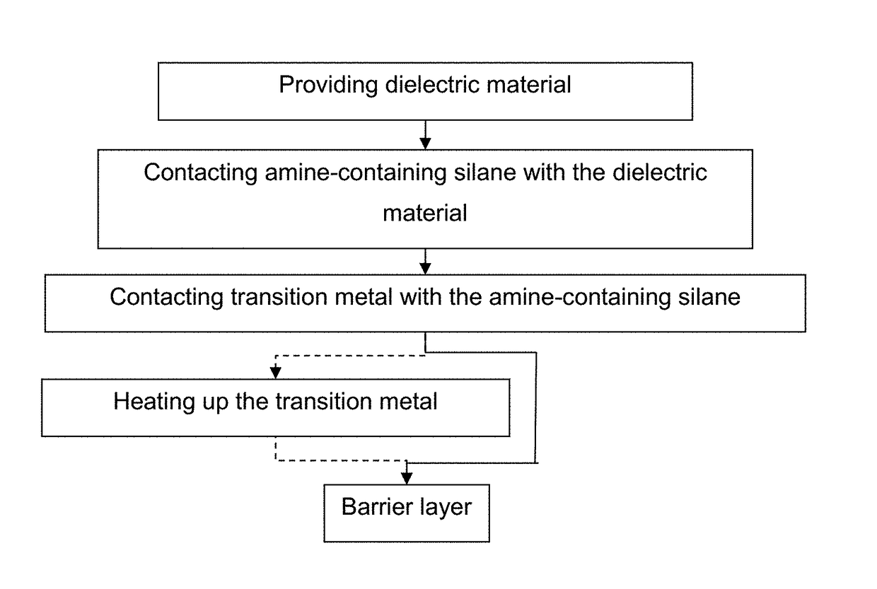
[0083]A plasma-enhanced chemical vapour deposited (PECVD) substrate was provided having a layer of porous silicon-based low-k material thereon. The porous silicon-based low-k material had a dielectric constant of 2.4. A pattern of trenches was defined in the layer of low-k material. The exposed surfaces, such as the side walls of the trenches, were then made more hydrophilic by a 2 to 3 s exposure to a CO2 plasma. A SAM of DETA was formed, either from the liquid phase or from the vapour phase, on the side walls of the trenches, at least partially sealing the pores of the porous low-k material. Subsequently, manganese (example 1a) or manganese nitride (example 1 b) was deposited on the SAM using chemical vapour deposition and a 200-400° C. thermal annealing was performed to complete the reaction of the manganese with the SAM; thereby forming a manganese barrier layer comprising manganese nitride. Finally, copper was d...

example 2

of a Ruthenium Nitride Barrier Layer for Use in a Damascene Process

[0087]A substrate was provided having a layer of porous organosilicate low-k material thereon. In one case, the low-k material had a dielectric constant of 2.4; in another, the dielectric constant was 2.55. A pattern of trenches and vias was defined in the layer of low-k material. The exposed surfaces, such as the side walls of the trenches, were then made more hydrophilic by a 2 to 3 s exposure to a CO2 plasma. A SAM of DETA was formed, from the vapour phase, on the side walls of the trenches, at least partially sealing the pores of the porous low-k material. Subsequently, a 20-25 nm thick layer of ruthenium was deposited on the SAM using atomic layer deposition and a 200-400° C. thermal annealing was performed to complete the reaction of the ruthenium with the SAM. Finally, copper was deposited inside the trenches covered with the ruthenium barrier layer. This deposition was performed by means of a (dual) damascene...


PUM

PropertyMeasurementUnit
temperatureaaaaaaaaaa
thicknessaaaaaaaaaa

Abstract

A use of an amine-containing silane for forming a transition metal nitride is provided. In this use, the amine of the amine-containing silane is the source of at least some, preferably most and most preferably all of the nitrogen present in the transition metal nitride.

Description

INCORPORATION BY REFERENCE TO RELATED APPLICATION[0001]Any and all priority claims identified in the Application Data Sheet, or any correction thereto, are hereby incorporated by reference under 37 CFR 1.57. This application claims the benefit of EP Application No. 16183450.2, filed on Aug. 9, 2016. The aforementioned application is incorporated by reference herein in its entirety, and is hereby expressly made a part of this specification.FIELD OF THE INVENTION[0002]Transition metal nitrides and in particular to the transition metal nitrides usable in barrier layers, used in the fabrication of interconnections in integrated circuits are provided.BACKGROUND OF THE INVENTION[0003]Within the field of (metal) interconnect fabrication in integrated circuits, transition metal layers, such as layers comprising manganese, are very interesting as barrier layers. US20110163062 A1 for example describes the use of manganese, chromium, vanadium or cobalt layers for preventing copper diffusion ou...

Claims


Application Information

Patent Timeline
Patent Type & Authority Applications(United States)
IPC IPC(8): H01L21/768H01L23/522H01L23/532
CPCH01L21/76843H01L21/76877H01L23/5226H01L23/53238C23C16/0272C23C16/045C23C16/34C23C16/56H01L21/76814H01L21/76826H01L21/76831H01L21/76864
Inventor ARMINI, SILVIA
Owner INTERUNIVERSITAIR MICRO ELECTRONICS CENT (IMEC VZW)
Why Eureka
Try Eureka