Method for tuning one or more resonator(s)

a technology of resonators and resonators, applied in the field of micro and nanophotonic resonators, can solve the problems of no better than a few nanometers precision, easy removal of fabricated optical resonators, and difficulty in high-precision construction, and achieve the effect of simple and non-degrading, easy removal

Active Publication Date: 2018-03-01
CENT NAT DE LA RECHERCHE SCI +1
View PDF2 Cites 1 Cited by
  • Summary
  • Abstract
  • Description
  • Claims
  • Application Information

AI Technical Summary

Benefits of technology

[0059]The permanence of the tuning is a major advantage for an industrial application, and the method allows for a broad range of wavelength tuning, from picometers to hundreds of nanometers.
[0060]Over the prior art, moreover the method does not require any additional co

Problems solved by technology

Micro- and nanoresonators are small devices, which are difficult to build with a high precision.
Industrials have developed clean room fabrication techniques (such as photolithography and plasma etching) that typically result in a precision no better than a few nanometers.
These reproducibility constraints due to the manufacturing-related imprecisions ultimately affect the ultimate resonance wavelength of the fabricated optical resonators.
As a result, fabricating several high Q, wavelength-sized optical resonators sharing exactly the same resonance wavelength is not currently achievable, even through state-of-the art fabrication means.
153303, 2010.In this document, a thin photochromic layer is deposited on the resonator.This technique has a limited tuning range, the layer can degrade optical and mechanical properties of the device, and is non-applicable for a plurality of resonators.M.
166-168, 2001.In this document, a mechani

Method used


Image

  • Method for tuning one or more resonator(s)
  • Method for tuning one or more resonator(s)
  • Method for tuning one or more resonator(s)

Examples


Embodiment Construction

[0090]In order to give a detailed view of the method, the specification will be based on a special type of resonator. This shall not be limitative, in so far as the method can be applied to any optical resonator. By resonator, it is meant any kind, or any shape, or any material that would enable a photonic resonance and the confinement of light in a given volume.

The Photonic Device

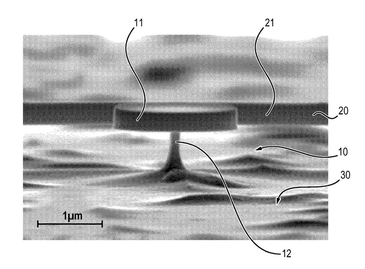
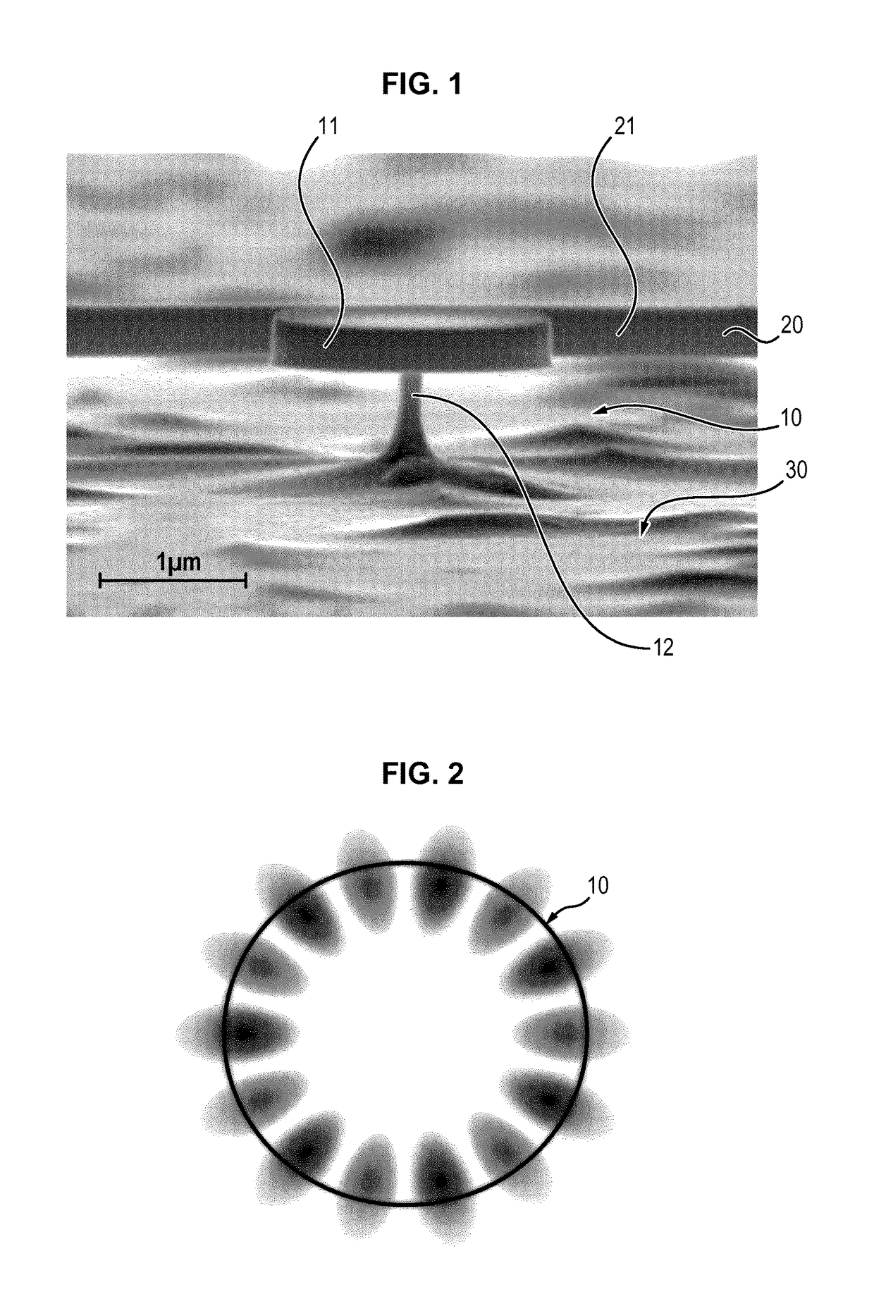
[0091]The nano- or micro-photonic resonant cavities, or photonic resonators 10, hereby referred as the resonator 10, employed here for proof of principle experiments consist of disks 11 (see FIG. 1), made from a semi-conductor such as Gallium Arsenide (GaAs). A disk is typically micrometer-sized in lateral dimensions and few hundreds of nanometers thick. The resonator 10 is coupled to an integrated optical waveguide 20, whose central region 21 is tapered in the vicinity of the resonator 10 to allow optical coupling. Typically, and not only in the disk case, said coupling is achieved by evanescent waves. Th...


PUM


Abstract

The invention concerns a method for tuning at a targeted resonance wavelength at least one micro and/or nanophotonic resonator, the resonator having dimensions defining resonance wavelength of said resonator, the resonator being immersed in a fluid containing ions so that the resonator is surrounded by said fluid, wherein the method comprises a step of injecting light, having a light wavelength equal to the resonance wavelength, into the resonator, so that the injected light resonates within the resonator and triggers a photo-electrochemical etching process enabled by the surrounding fluid containing ions, said etching process being enhanced by the optical resonance which amplifies light intensity in the photonic resonator, the etching decreasing dimensions of the photonic resonator, hereby lowering and tuning the resonance wavelength of the photonic resonator.

Description

FIELD OF THE INVENTION[0001]The invention relates to the field of micro- and nano-photonic resonators and in particular to the tuning of such resonators to a desired wavelength.[0002]Optical resonators, which are part of a photonic device, generally consist in a cavity in which light can enter and resonate, hereby amplifying the signal.PRIOR ART[0003]Micro- and nanoresonators are small devices, which are difficult to build with a high precision. Industrials have developed clean room fabrication techniques (such as photolithography and plasma etching) that typically result in a precision no better than a few nanometers. These reproducibility constraints due to the manufacturing-related imprecisions ultimately affect the ultimate resonance wavelength of the fabricated optical resonators.[0004]As a result, fabricating several high Q, wavelength-sized optical resonators sharing exactly the same resonance wavelength is not currently achievable, even through state-of-the art fabrication m...

Claims


Application Information

Patent Timeline
IPC IPC(8): G02B27/00G02B5/18G02B6/136G02B6/12
CPCG02B27/0012G02B5/1857G02B6/136G02B6/12007G02B5/28G02B1/005G02B6/29338G02B6/29341
Inventor FAVERO, IVANBAKER, CHRISTOPHERGIL SANTOS, EDUARDO
Owner CENT NAT DE LA RECHERCHE SCI
Why Eureka
Try Eureka