Nondestructive inspection method for coatings and ceramic matrix composites

Active Publication Date: 2018-05-03
GENERAL ELECTRIC CO
View PDF3 Cites 11 Cited by
  • Summary
  • Abstract
  • Description
  • Claims
  • Application Information

AI Technical Summary

Benefits of technology

The invention allows for a scan to be performed on a surface with a pulse that covers a wide range of frequencies. This scan can find anomalies in three dimensions. The pulse can also be filtered to improve resolution, allowing for evaluation across a narrower band of frequencies. Overall, the invention can provide a more accurate and precise scan for inspecting surfaces.

Problems solved by technology

The limitations of visual inspection are that it cannot disclose indications that are below the surface of the exterior of the object under inspection and hidden from sight.
Visual inspection also may not be able to resolve very small indications that may be open to the exterior surface of the object.
The limitations of the liquid penetrant inspection are that the indications must be open to the surface and the indications must be fairly small with tight openings to the surface, as a shallow, large indication will have penetrant removed when the surface is wiped clean.
The limitation of the eddy current technique is that it can only detect indications near the surface of the object under inspection (referred to as near surface indications), as the eddy current is a surface current that does not otherwise penetrate into the object.
Magnetic particle inspection is limited to ferrous articles.
The limitations of the magnetic particle penetrant inspection are that the article that is to be inspected must be magnetizable, typically ferrous, indications must be open to the surface and the indications must be fairly small, as a shallow, large indication will have penetrant removed when excess penetrant is removed from the surface.
In addition, when contact electrodes are used by the technician to apply the current to the surface of the article, it is possible that arc strikes may occur to the article surface if care is not exercised by the technician.
These arc strikes may in certain applications be deemed as damage.
More of the high energy waves are absorbed dense materials, so materials such as tungsten do not allow the same quantity of waves through as for example, porosity or cracks, which transmit all of the waves.
Limitations are that radiographic inspection is not very useful for detecting imperfections in multi-phase materials such as precipitation hardened materials.
The precipitates usually are of a different density than the base material, and the relatively uniform distribution of particles make it very difficult to discern an indication in the base material and distinguish it from precipitates.
In addition, flat or plate-like indications, when oriented perpendicular to the direction of the incident x-rays also can be difficult to detect, particularly when the thickness of the indication when compared to the overall thickness of the material being inspected is small.
Ultrasonic inspection is utilized with surface inspection techniques such as liquid penetrant or magnetic particle inspection since ultrasonic inspection is limited in its ability to resolve surface indications due to the large front pulse reflection and back surface reflections.
In addition, the frequency of the ultrasonic waves limits the size of the indication that can be resolved.
One of the limitations of ultrasonic inspection is that it may not be able to resolve small indications in the path of the applied wave simply because a small indication may not reflect sufficient energy, or the amount of reflective energy may not be a true representation of the size of the indication.
Another limitation of ultrasonic inspection is that it cannot be utilized to inspect precipitation hardened materials, simply because precipitates reflect ultrasonic energy making it impossible to discern any anomalous indications and distinguish them from the precipitates.
Similarly, materials including multiple phases, such as particles suspended in a metallic matrix also cannot be inspected due to the reflected energy.
The ultrasonic techniques have also required a liquid couplant between the transducer / transceiver and the article, because air is a poor transmitter of ultrasonic energy.
While inspection techniques, such as the ones described above are available for use to test the adequacy of metal structures, aside from visual inspection, the same techniques are not available to detect anomalies in CMC structures used in aircraft structures.

Method used


Image

  • Nondestructive inspection method for coatings and ceramic matrix composites
  • Nondestructive inspection method for coatings and ceramic matrix composites
  • Nondestructive inspection method for coatings and ceramic matrix composites

Examples


Embodiment Construction

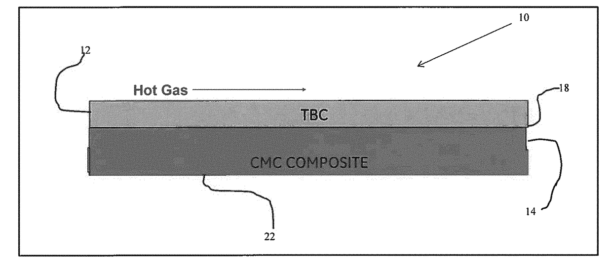
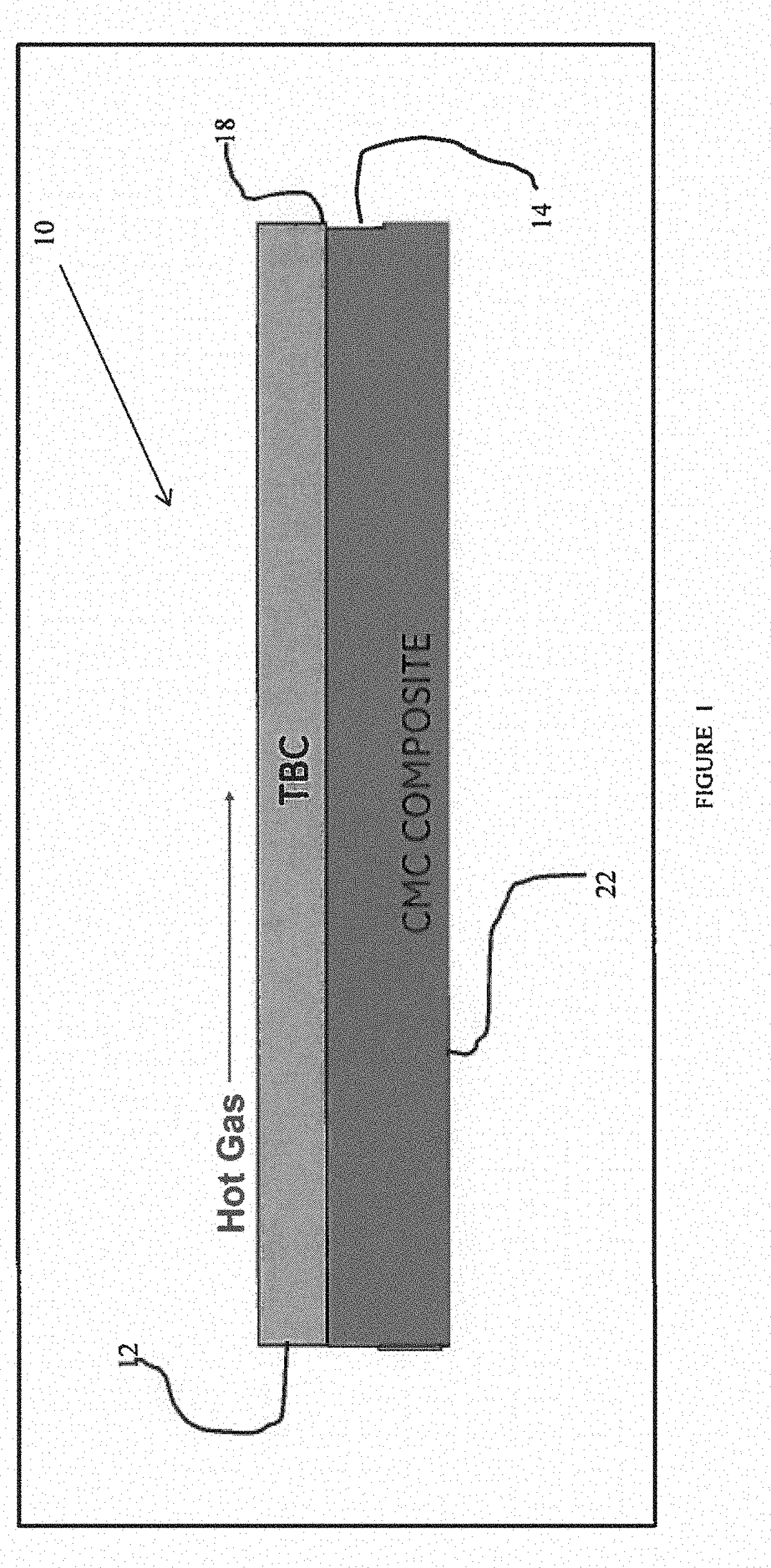
[0024]A nondestructive inspection (NDI) or test (NDT) method for use with coating systems and nonmetallic structures such as ceramic matrix composite (CMC) material structures and polymer or polymeric matrix composite material (PMC) structures is set forth. The test also may be used to evaluate nonmetallic coatings overlying metallic structures. This test method utilizes electromagnetic waves in the Terahertz frequency range, referred to hereinafter as Terahertz testing, and finds particular use with multilayer nonmetallic systems including ceramic structures having one or more nonmetallic coating layers. The ceramic structure itself may comprise multiple layers of ceramic material, multiple layers of CMC material or mixed structures comprising ceramic layers and CMC layers. The test method also finds use with ceramic layers that comprise a matrix having substantially uniformly distributed particles or features within the matrix, such as coating systems that include fine porosity ad...


PUM


Abstract

A method for nondestructive inspection of ceramic structures present as either a ceramic matrix composite structure or a ceramic based coating. Such non-metallic structures are used to provide thermal protection or weight reduction or both to aircraft and their components. The nonmetallic structure is scanned with an electromagnetic pulse in the range of 200 GHz to 4 THz. The electromagnetic pulse includes a plurality of frequencies within the Terahertz range and is not restricted to a single designated frequency. The frequency range is sensitive to changes in impedances and refractive index within the structure. After the electromagnetic pulse passes through the nonmetallic structure, it may be evaluated for changes in impedance in the nonmetallic structure at different locations, and, when present, whether the changes in impedance impact the ability of the structure to perform the function for which it was designed.

Description

FIELD OF THE INVENTION[0001]The present invention is directed to nondestructive inspection methods and specifically to nondestructive inspection methods for coating systems and ceramic matrix composite materials.BACKGROUND OF THE INVENTION[0002]Various inspection methods are available to detect indications in materials. These indications are anomalies in materials and may be classified as defects if the anomalies are serious enough to be categorized as a problem during the life of the component of which the material is comprised. When the indications are not serious, they may be classified as acceptable anomalies as their size and shape have been evaluated and deemed not to affect the operation of the component over its useful life.[0003]There are various inspection techniques available. Some of these include visual inspection, eddy current inspection, liquid penetrant inspection, magnetic particle inspection, ultrasonic inspection and radiographic inspection. Each of these techniqu...

Claims


Application Information

Patent Timeline
IPC IPC(8): G01N27/02G01N21/95
CPCG01N27/02G01N2201/105G01N2201/0696G01N21/95G01N22/02G01N21/3563G01N21/3581G01N21/8422G01B11/0616G01R27/26G01N27/4162G01R27/20G01R15/144G01R15/12G01R19/00G01R19/30G01R21/06G01R31/2623
Inventor BAUCKE, RUSSELL CRAIGHILDERBRAND, GLEN DAVIDDECKER, TIMOTHY FRANCISCROWGEY, BENJAMIN REID
Owner GENERAL ELECTRIC CO
Why Eureka
Try Eureka