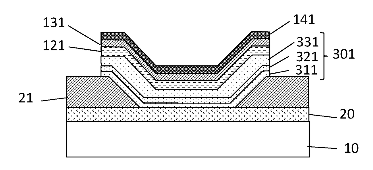
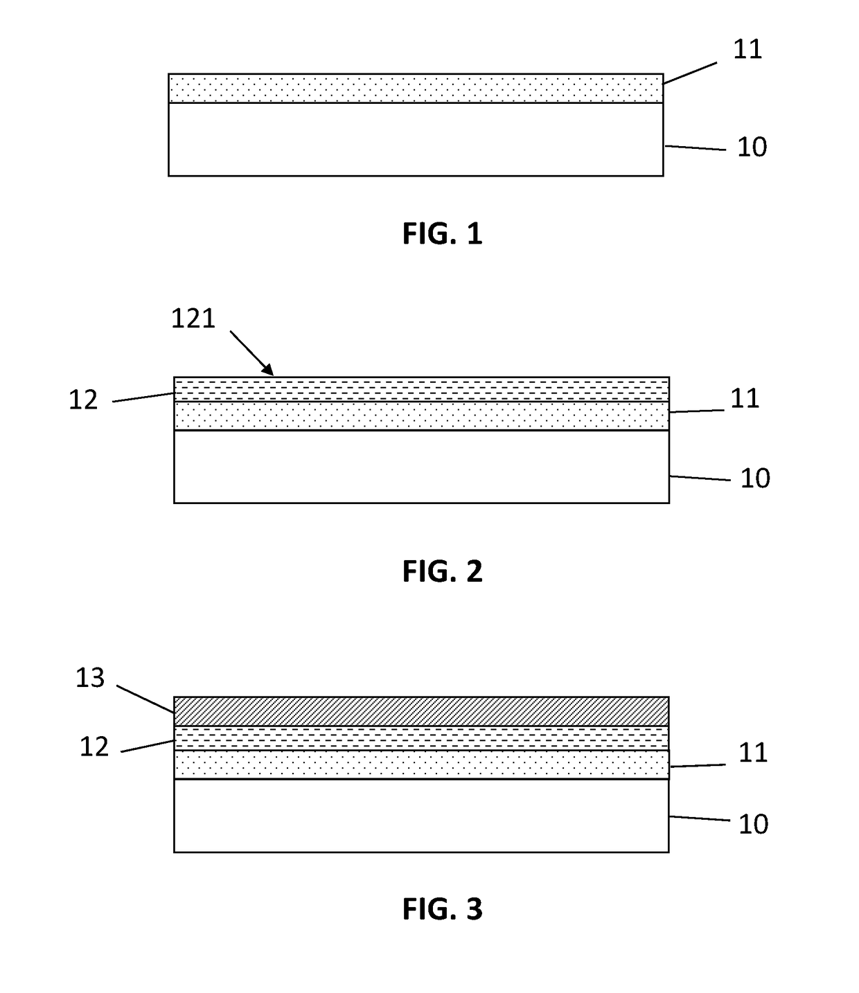
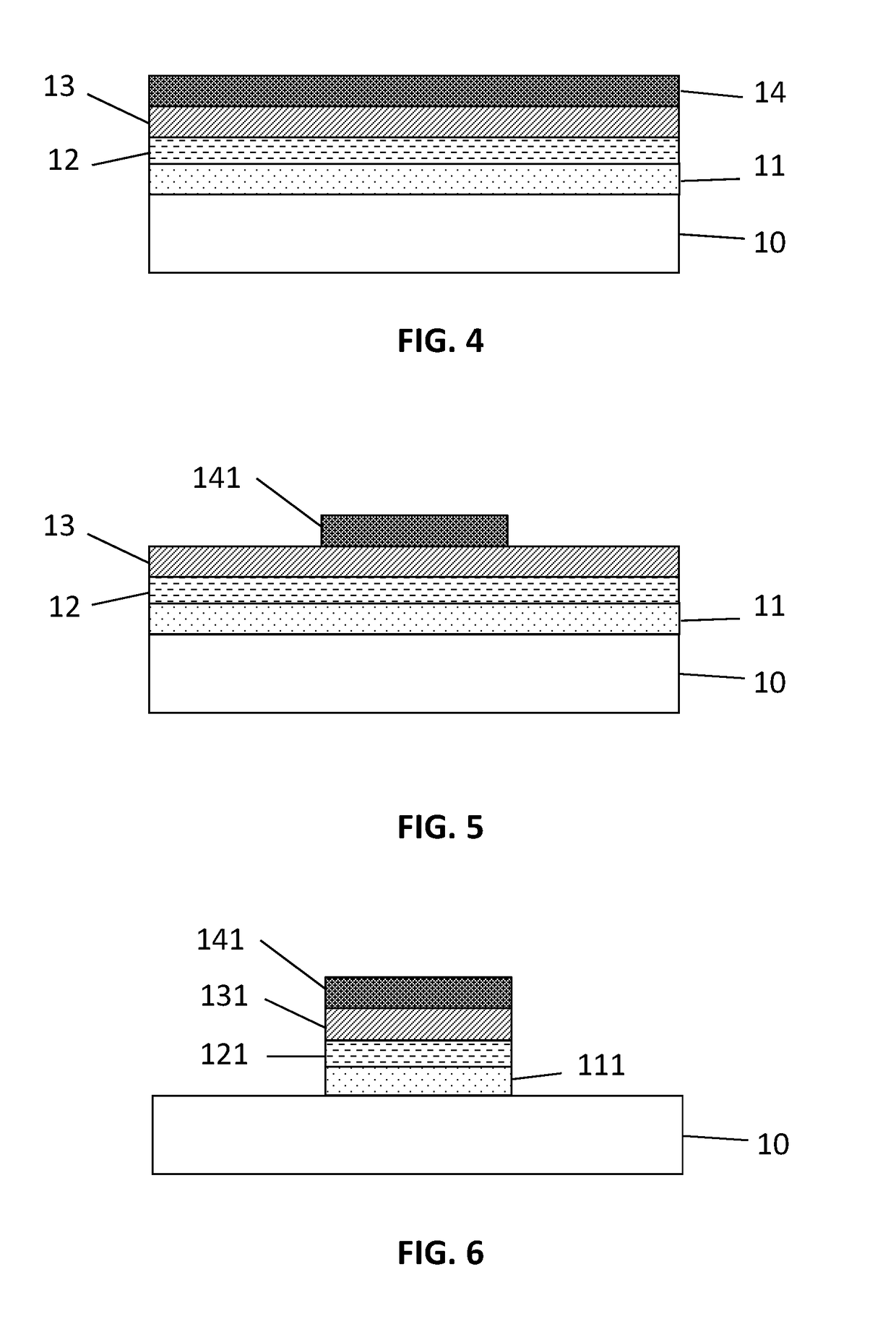
Method for High Resolution Patterning of Organic Layers

a technology of organic layers and organic semiconductors, applied in the field of organic electronics, can solve the problems of water penetration into the organic layer, the limitation of the current available, and the use of photolithographic processes in combination with organic semiconductors is not straightforward, so as to achieve high resolution, up-scalable

Active Publication Date: 2018-07-05
INTERUNIVERSITAIR MICRO ELECTRONICS CENT (IMEC VZW) +1
View PDF8 Cites 10 Cited by
  • Summary
  • Abstract
  • Description
  • Claims
  • Application Information

AI Technical Summary

Benefits of technology

[0031]It is an advantage of a method in accordance with embodiments of the present invention that it allows using conventional photolithographic products (photoresists, developers) already used in the microelectronics industry. It is an advantage that there is no need for using expensive products such as fluorinated photoresists.
[0032]It is an advantage of a method in accordance with embodiments of the present invention that the hydrophobic protection layer reduces water intake in the underlying organic layers and protects the underlying organic layers during the photolithographic process. It is an advantage that this may result in a substantially longer operational lifetime of a patterned organic device such as a patterned OLED as compared to an organic device that is patterned without using a hydrophobic protection layer.
[0033]It is an advantage of a method in accordance with embodiments of the present invention that it is up-scalable and that it is compatible with existing semiconductor process lines.
[0034]It is an advantage of a method in accordance with embodiments of the present invention that the highest processing temperature used for patterning of the organic layer may be below 150° C., or even below 110° C. Therefore the method may be used on flexible foil substrates such as for example a polyethylene naphthalate (PEN) foil or a polyethylene terephthalate (PET) foil, thus enabling the fabrication of flexible organic devices and circuits with high resolution.
[0035]It is an advantage of a method in accordance with embodiments of the present invention that it may be cost effective and well controllable.
[0036]It is an advantage of a method in accordance with embodiments of the present invention that it may be used for patterning organic layers that degrade when exposed to water, the method avoiding or strongly reducing the risk of such degradation.

Problems solved by technology

One of the bottlenecks of known methods for the fabrication of organic electronic devices may be related to the limitations of currently available patterning techniques.
However, using a photolithographic process in combination with organic semiconductors is not straightforward, because most of the solvents used within standard photoresists, as well as the solvents used for resist development and / or resist stripping may dissolve the organic layers.
However, applying such an approach may involve a risk that water penetrates into the organic layer and causes damage to or degradation of the organic semiconductor layer, such as for example a reduction of the carrier mobility, morphological changes, or interface contamination.
When patterning such layers using photolithography in combination with a water soluble or water based shielding layer, water may penetrate into the OLED stack, resulting in degradation of the device, e.g. a reduction of the operational lifetime, a reduction of the emission quantum efficiency, a reduction of power efficiency and / or changes in the colour emitted by the OLEDs.
For other organic semiconductor devices similar degradation mechanisms may occur, leading for example to a reduction of the efficiency of organic photodetectors or organic photovoltaic cells.

Method used


Image

  • Method for High Resolution Patterning of Organic Layers
  • Method for High Resolution Patterning of Organic Layers
  • Method for High Resolution Patterning of Organic Layers

Examples


Embodiment Construction

[0049]The present invention will be described with respect to particular embodiments and with reference to certain drawings but the invention is not limited thereto but only by the claims. The drawings described are only schematic and are non-limiting. In the drawings, the size of some of the elements may be exaggerated and not drawn on scale for illustrative purposes. The dimensions and the relative dimensions do not correspond to actual reductions to practice of the invention.

[0050]Furthermore, the terms first, second and the like in the description and in the claims, are used for distinguishing between similar elements and not necessarily for describing a sequence, either temporally, spatially, in ranking or in any other manner. It is to be understood that the terms so used are interchangeable under appropriate circumstances and that the embodiments of the invention described herein are capable of operation in other sequences than described or illustrated herein.

[0051]It is to be...


PUM


Abstract

At least one embodiment relates to a method for photolithographic patterning of an organic layer on a substrate. The method includes providing a water-soluble shielding layer over the organic layer. In addition, the method includes providing a photoresist layer on the water-soluble shielding layer. The method also includes photolithographic patterning of the photoresist layer to form a patterned photoresist layer. Further, the method includes etching the water-soluble shielding layer and the organic layer, using the patterned photoresist layer as a mask, to form a patterned water-soluble shielding layer and a patterned organic layer. Still further, the method includes removing the patterned water-soluble shielding layer. The method includes, before providing the water-soluble shielding layer, providing a hydrophobic protection layer having a hydrophobic upper surface on the organic layer.

Description

FIELD OF THE INVENTION[0001]The present invention relates to the field of organic electronics. More specifically, it relates to methods for high-resolution patterning of organic layers, such as organic semiconductor layers, by means of photolithography, and to methods for fabricating organic electronic devices comprising an organic semiconductor layer patterned by photolithography.BACKGROUND OF THE INVENTION[0002]Organic electronics research is steadily growing, with developments in materials, processes and system integration. Applications such as organic photovoltaic cells (OPV), organic photodetectors (OPD), organic thin-film transistors (OTFT) and especially organic light-emitting diodes (OLED) for lighting and displays are leading the way to industrialization.[0003]One of the bottlenecks of known methods for the fabrication of organic electronic devices may be related to the limitations of currently available patterning techniques.[0004]A particularly promising technique to achi...

Claims


Application Information

Patent Timeline
Patent Type & Authority Applications(United States)
IPC IPC(8): H01L51/00H01L51/56H01L51/42H01L51/05
CPCH01L51/0018H01L51/56H01L51/42H01L51/0508H01L51/0085Y02E10/549H10K71/233H10K10/46H10K85/342H10K30/00H10K71/00
Inventor KE, TUNG HUEIMALINOWSKI, PAWELNAKAMURA, ATSUSHI
Owner INTERUNIVERSITAIR MICRO ELECTRONICS CENT (IMEC VZW)
Why Eureka
Try Eureka