Method and systems relating to construction material assessment

a technology of construction material and assessment method, applied in the direction of structural/machine measurement, material impedance, instruments, etc., can solve the problems of wrong side of the road surface being ripped up, inconvenient to carry around, and the matrix of embedded sensors across say even a 100 m10m bridge is prohibitiv

Active Publication Date: 2018-08-23
GIATEC SCI
View PDF6 Cites 59 Cited by
  • Summary
  • Abstract
  • Description
  • Claims
  • Application Information

AI Technical Summary

Benefits of technology

[0022]It is an object of the present invention to address limitations within the prior art relating concrete testing and concrete structure characterization, more particularly to electrical methods and systems for establishing cured concrete performance from measurements of wet concrete, automated methods and systems for periodic and / or continuous characterization of concrete structures, electrical methods and systems for corrosion measurement of rebar in reinforced concrete structures, construction material process monitoring and compact self-contained electrical sensors with wireless interfaces.

Problems solved by technology

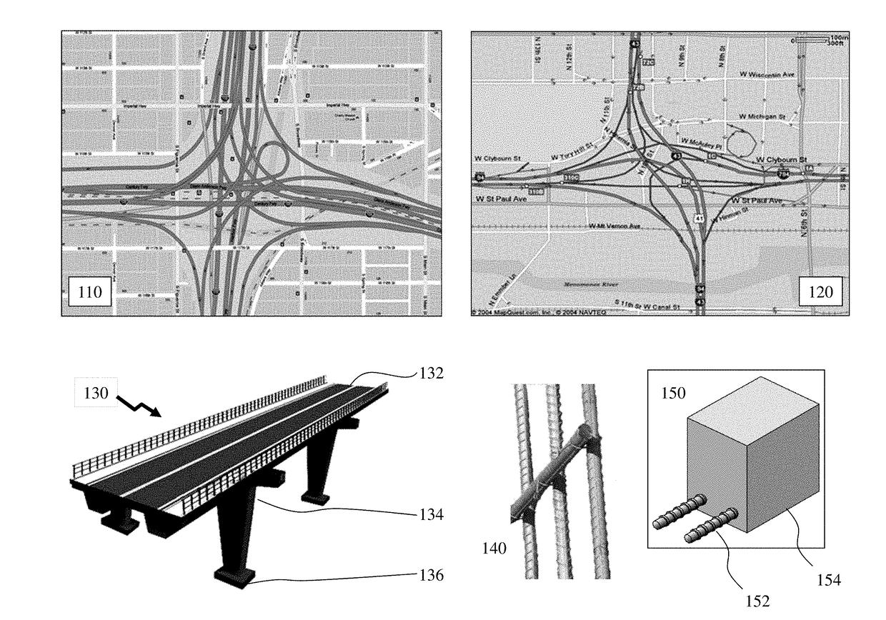
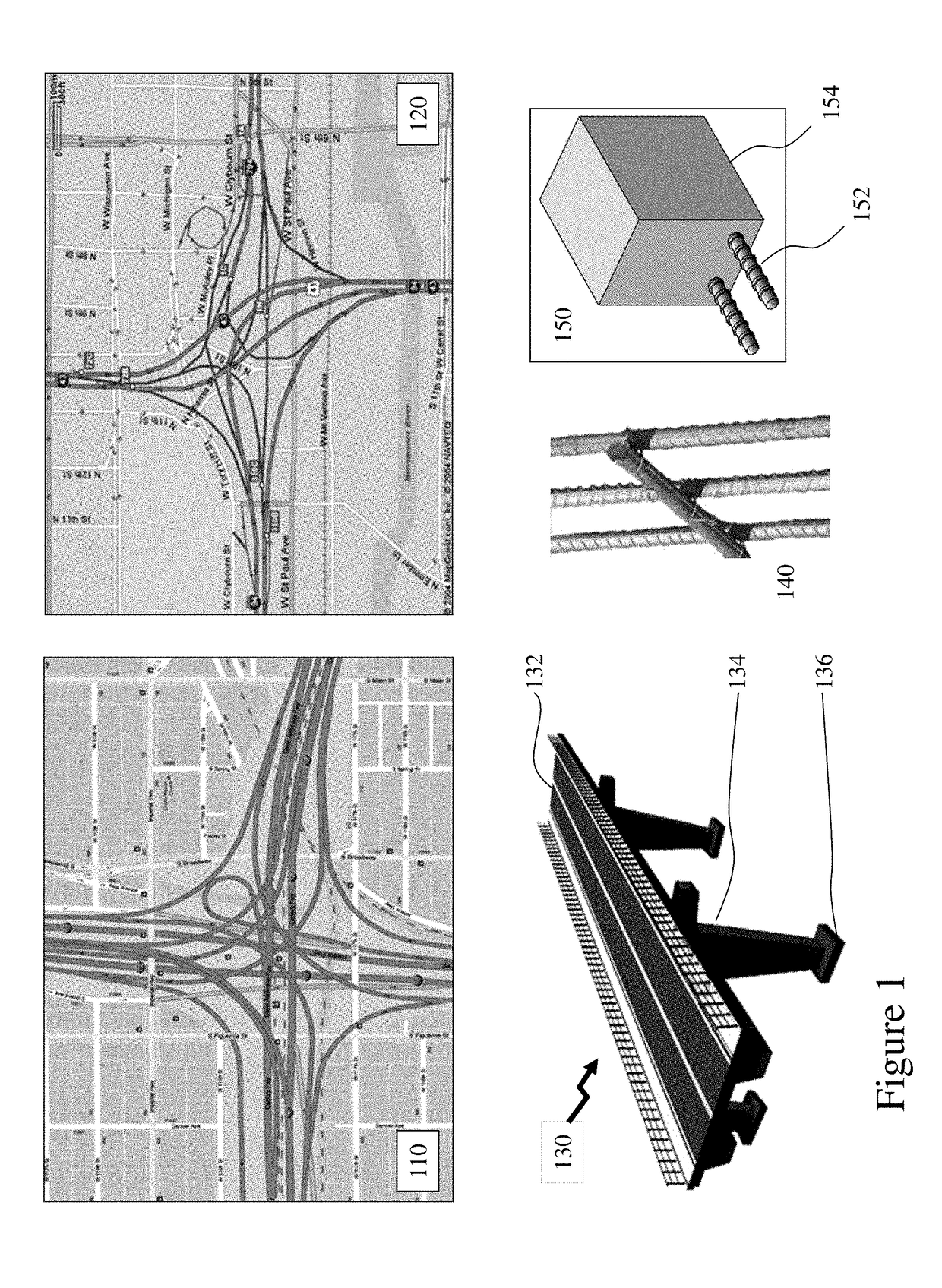
Whilst perhaps overly dramatic these are just two of the 600,000 bridges and millions of buildings in the US requiring characterization for corrosion.
A work crew returning may be addressing a small area but without alignment to the physical structure the measurements provide no additional benefit and accordingly it is likely that the physical intervention will involve a substantial portion of the road surface.
Likewise, a simple error in denoting which side of the road the measurements were made on results in the wrong side of the road surface being ripped up.
However, these embedded sensors are expensive individually and deploying a matrix of them across say even a 100 m×10m bridge prohibitive even without considering the additional complexities of interface cabling, measurement electronics etc.
The measurement of steel corrosion potential inside concrete directly below the surface 0020 of an insulating material such as asphalt or tarmac is not possible.
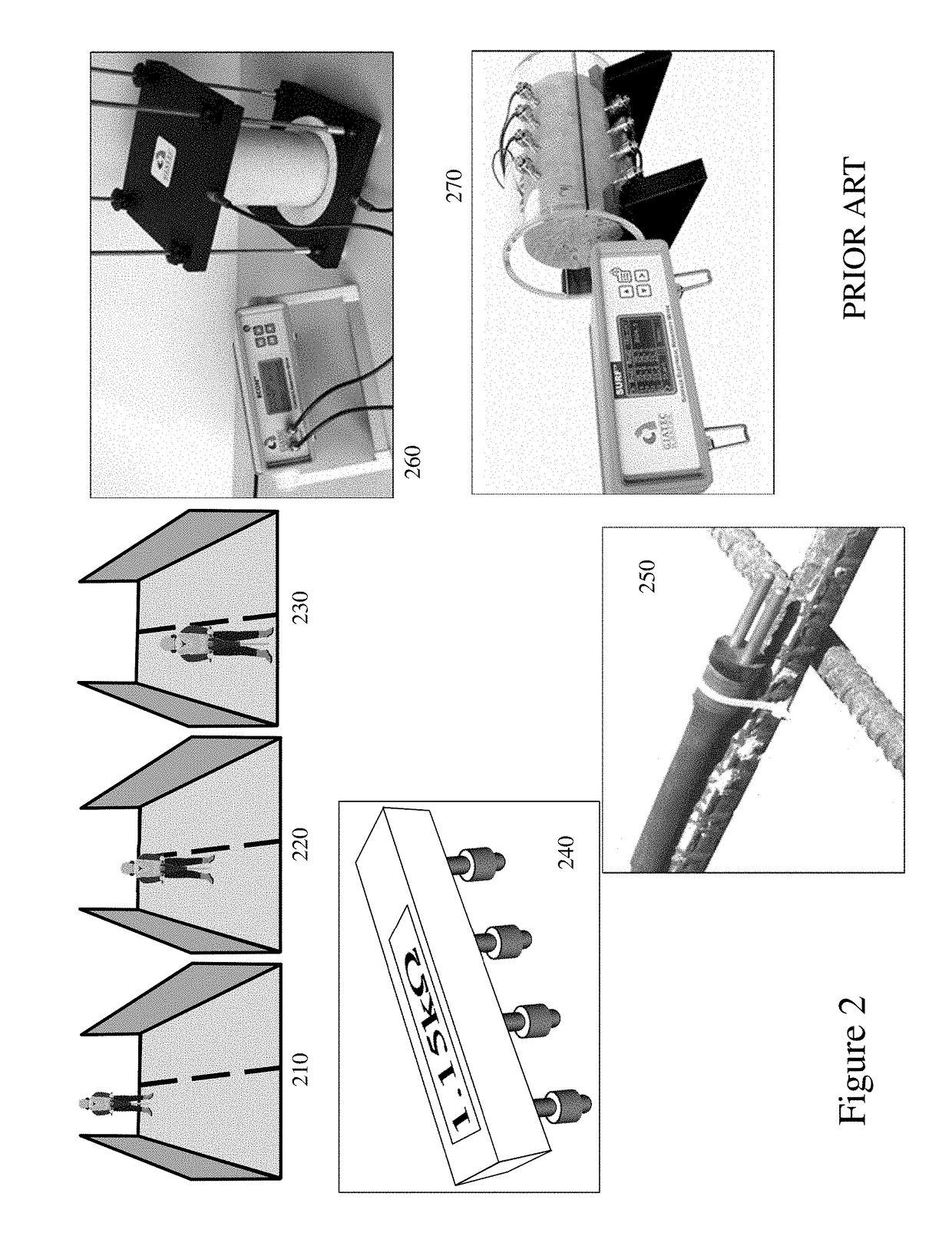
However, direct measurement of the low-frequency impedance of rebar in concrete is very time-consuming and vulnerable to noise interruption as discussed supra; hence it is not practical to use this technique in the field to measure the corrosion rate of rebar inside the concrete.
Higher water content increases the porosity of the hardened concrete and thus decreases its strength and durability but low water content, in contrast, decreases the workability of concrete.
In the latter, the ingress of aggressive ions such as chlorides into the pore structure of concrete increases the conductivity of the pore solution and thus decreases the electrical impedance of concrete.
However, rebar(s) within the concrete can disturb the electrical resistivity measurements and accordingly the recommended measurement orientation of the 4-point Wenner / Schlumberger probes is determined by the spacing of the rebars as ideally the orientation is diagonal to the square matrix of rebars but if this not possible then the orientation should be perpendicular to the rebar.
However, in the case of passive, non-corroded, rebar because of the high polarization resistance of the passive layer on the surface of the rebar the current passage through the rebar would be very limited, and therefore, increases over time as a result of polarization, i.e. charge of double layers of capacitors.
However, even these measurements whilst advancing the data and information available to the construction team, architect, quality management, surveyor, regulatory authority etc. have limitations with respect to the number that can be used, their locations, etc. and the fact that the measurements taken may require detailed data such as a maturity calibration curve from the concrete producer.
Further, an essential portion of the “chain” is still not captured and accordingly pre-acceptance testing of the concrete may still be necessary prior to its being poured at the site.
Early, rapid and accurate in-situ estimation of the compressive strength of concrete is one of the major challenges for the concrete industry.
Lack of an accurate estimation of strength at early ages of construction is twofold: contractors either wait too long for next action (e.g. stripping formwork) which is costly due to delays in completing the project, or they act prematurely which could cause the concrete structure to crack—that would lead to future durability and performance issues—or even structural collapse.
The problem, however, is that only one specimen is crushed for strength estimation.
This method is limited to use in horizontal and thick concrete elements like slabs.
This adds to the cost of construction and its uncertainty decreases the efficiency of the construction.
Although alternative methods such as concrete maturity exist, there is a traditional resistance to utilizing them for most concrete projects.
Such approaches to compressive strength evaluation may cause concrete contractors to make conservative decisions, face more complicated technical problem (e.g. delay in formwork stripping, and unnecessary long-term curing and surface protection), and spend more financial resources.
Any deviations from the original mix design (such as water to cement ratio, cement content, etc.) will reduce the accuracy of the maturity method to estimate the compressive strength.
Some of important limitations of this method are listed as follows:In-place concrete is not representative of the concrete used to develop the calibration in the lab.
;In-place concrete is not properly placed, consolidated, cured, etc.
;Very high early-age temperatures can lead to inaccurate estimation of strength at later ages;Using a datum temperature (for the Nurse-Saul function) that is not representative of the concrete mixture can result in incorrect estimation of strength.
This is mainly due to the upfront cost of concrete mixture calibration for maturity curves, and lack of expertise for the installation of concrete temperature sensors, data collection and analysis.
However, the electrical resistivity measured is also impacted by the presence of humidity and the water content of the concrete.
However, the conductivity of mixing water changes throughout mixing due to an ongoing chemical interaction with cement and chemical admixtures.
Accordingly, these scenarios result in the challenge of properly identifying the location of the SMAK.
These may, for example, be a restriction on how long formwork can be left up after construction material is poured, how much material is required, time limits for delivery and pouring as the location may be within a busy downtown core, an issue from another aspect of the project etc.
Further, as this may be problematic for some or all deliveries the admixture(s) may be preloaded into one or more dispensers which are automatically triggered based upon downloading of a program to the concrete truck from the database for a specific delivery batch.
Equally, such analysis may determine that a batch having been loaded for two hours reaches a point where subsequent deployment will result in reduced performance or that the current projected environmental conditions will require all loads to be poured within a predetermined period of time if the concrete is required as a single contiguous block rather than multiple layers as a second pour is made upon a curing previous pour etc.

Method used


Image

  • Method and systems relating to construction material assessment
  • Method and systems relating to construction material assessment
  • Method and systems relating to construction material assessment

Examples


Embodiment Construction

[0148]The present invention is directed to concrete testing and more particularly to electrical methods and systems for measuring rebar corrosion in reinforced concrete structures

[0149]The ensuing description provides exemplary embodiment(s) only, and is not intended to limit the scope, applicability or configuration of the disclosure. Rather, the ensuing description of the exemplary embodiment(s) will provide those skilled in the art with an enabling description for implementing an exemplary embodiment. It being understood that various changes may be made in the function and arrangement of elements without departing from the spirit and scope as set forth in the appended claims.

[0150]A “portable electronic device” (PED) as used herein and throughout this disclosure, refers to a wireless device that requires a battery or other independent form of energy for power. This includes devices including, but not limited to, cellular telephone, smartphone, personal digital assistant (PDA), po...


PUM

PropertyMeasurementUnit
bag weightaaaaaaaaaa
compressive strengthaaaaaaaaaa
depthaaaaaaaaaa

Abstract

Hundreds of thousands of concrete bridges, buildings etc. and hundreds of billions of tons of concrete require characterization throughout the process from manufacture to pouring and curing and on throughout service life. The characterization may relate to initial concrete properties, projected concrete properties, framework removal, corrosion, failure etc. Accordingly, a variety of measurements such as water content, electrical resistivity, and half-cell corrosion potential for example would be beneficially implemented as easy to use field test equipment or embedded sensors allowing lifetime monitoring to be performed rather than discrete assessments when issues become evident.

Description

CROSS-REFERENCE TO RELATED APPLICATIONS[0001]This patent application claims the benefit of priority as a continuation-in-part of U.S. patent application Ser. No. 15 / 496,298 filed Apr. 25, 2017 entitled “Electrical Methods and Systems for Concrete Testing”, which itself claims the benefit of priority as a continuation of U.S. patent Ser. No. 14 / 168,254 filed on Jan. 30, 2014 entitled “Electrical Methods and Systems for Concrete Testing”, which itself claims the benefit of priority from U.S. Provisional Patent Application 61 / 758,309 filed on Jan. 30, 2013 entitled “Electrical Methods and Systems for Concrete Testing”, the entire contents of each being included by reference.[0002]This patent application claims the benefit of priority as a continuation-in-part of U.S. patent application Ser. No. 15 / 311,055 filed Nov. 14, 2016 entitled “Electrical Methods and Systems for Concrete Testing”, which itself claims the benefit of priority from Patent Cooperation Treaty Application PCT / CA2015 / 0...

Claims


Application Information

Patent Timeline
Patent Type & Authority Applications(United States)
IPC IPC(8): G01N27/02G01N17/02G01N33/38
CPCG01N27/026G01N17/02G01N33/383G01L1/10G01L1/20G01L1/22G01N17/006G01N17/00G01M5/0008G01M5/0083G01N27/02G01N27/04G01R27/00
Inventor GHODS, POURIAALIZADEH, ROUHOLLAHSALEHI, MUSTAFASALEHI, SARAHFAHIM, ANDREW
Owner GIATEC SCI
Why Eureka
Try Eureka